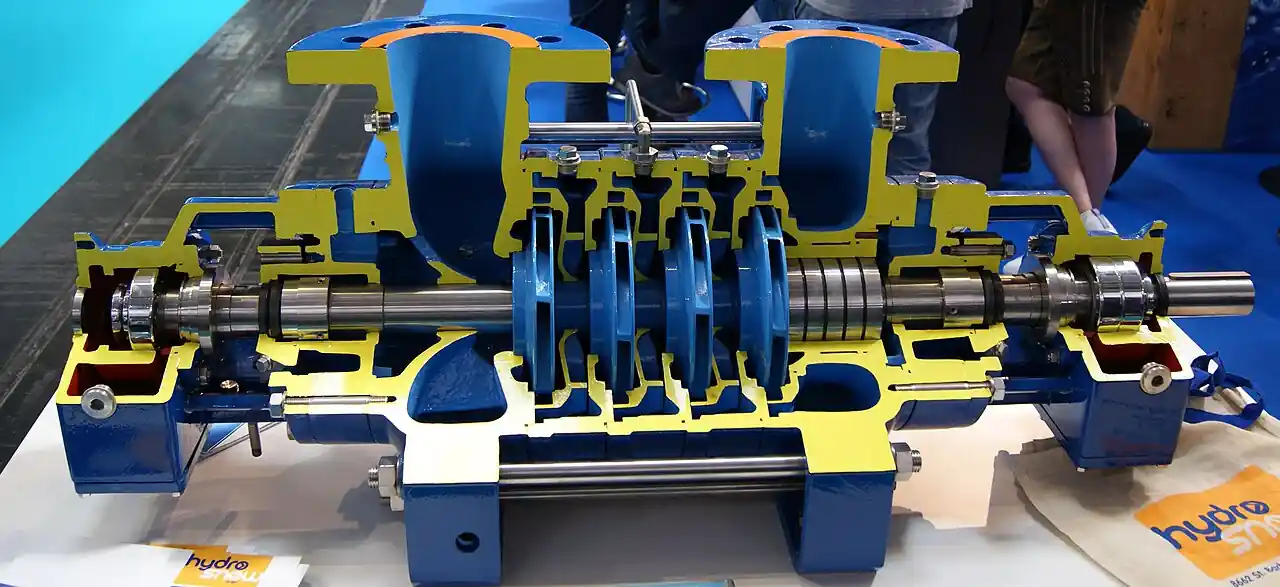
A regenerative turbine pump is a rotodynamic pump whose impeller is a disc rimmed with many short radial vanes machined into both faces. Liquid entering near the periphery is struck by the vanes, thrown outward into a shaped channel ring that surrounds the impeller, and then picked up again by a later vane, spiraling around the periphery in a helical path of roughly 360 degrees before it reaches the discharge port. Each pass through the vanes adds energy, so a single stage develops heads three to ten times what a centrifugal stage of the same diameter can reach. Catalogs sell the same machine as a peripheral pump, a side channel pump, or a vortex pump, and engineers shorten it to regen turbine; this page uses the names interchangeably and treats the family as one product.
Procurement engineers meet these pumps where the duty is low flow at high head on a small footprint: small boiler feed, hot condensate return at temperatures where other machines cavitate, water pressure booster sets, chemical transfer in sealless construction, and fuel or refrigerant circulation loops. The decision this page settles is whether this family is the right machine for a corner of the pump map that fills with poor alternatives: a centrifugal pump selected far below its best efficiency point, or a positive displacement machine brought in for pressure it does not otherwise need. The answer lands as an RFQ line set, flow, head, stages, materials, seal strategy, and test acceptance, and every chapter below feeds that line set.
This page treats the regenerative turbine pump as a purchasing object: what the peripheral impeller actually does to the fluid, how one stage reaches heads that shame a centrifugal stage, where the family's efficiency honesty and clearance sensitivity set its limits, how seal, sealless, and multistage constructions divide the duty, and how test acceptance and RFQ language pin the quotation down. It is written for engineers who issue purchase specifications, not for readers who want a brochure summary.
Chapter 1 / 06
What a Regenerative Turbine Pump Is and What Is Being Decided
The defining geometry is the impeller. Where a centrifugal impeller accelerates liquid once, from eye to tip along an open passage, the peripheral impeller carries dozens of narrow machined vanes on both faces of a flat disc, and the casing holds a channel ring around the rim with an inlet port and a discharge port separated by a stripper, a close fitting bridge that seals the channel's working arc from the discharge side. Liquid recirculates between vanes and channel many times in one journey around the periphery, gaining pressure incrementally with each cycle, in the way a multistage machine gains pressure stage by stage. That is the honest mental model: one physical stage behaving like a train of small stages.
The numbers that follow from the geometry are the family's identity. Small close coupled units reach 30 to 150 m of head at flows of 0.5 to 10 m3/h. The family window overall runs from about 0.2 to 30 m3/h in flow, with multistage versions building heads to roughly 300 m and working pressures to about 40 bar. A centrifugal pump covering the same head in one stage would need a physically enormous impeller running dangerously fast; a multistage pump covers it with genuine stages, more parts, and higher cost below roughly 15 m3/h. The regenerative turbine occupies that corner deliberately.
Efficiency is where the family must be defended honestly. Peak efficiency runs 35 to 50 percent, well below a centrifugal pump at its best efficiency point. But the comparison that matters is at the duty: below roughly a fifth of a centrifugal's rated flow, its efficiency collapses, its curve turns flat and unstable, and radial loads climb, while the regen turbine still sits near its own peak at exactly that low flow. The buyer is not choosing between efficiency values on two datasheets; the buyer is choosing which machine is efficient at the flow actually being pumped.
What is actually being decided in this purchase has four parts. First, duty fit: confirming the operating point is genuinely low flow and high head, and that the flow is steady rather than a transient corner of a wider range. Second, construction: single stage close coupled, multistage for deeper head, magnetic drive or canned motor construction when leakage cannot be tolerated. Third, fluid discipline: the family lives on tight internal clearances, so the specification must commit to strainer protection and to excluding abrasives, or choose a different family. Fourth, seal strategy: a mechanical seal in its classic form, or a sealless solution that removes the dry running failure mode entirely.
The boundary against neighbors can be drawn once here and revisited with numbers in chapter 5. Above roughly 15 to 30 m3/h of flow, or when efficiency targets rise with flow, the centrifugal and multistage families take over. Above roughly 40 bar, or on viscous fluids, the gear pump and plunger pump families own the ground. Water arriving from wells and wet sumps belongs to the vertical turbine pump, a different geometry built around a different source. For proportional chemical dosing the metering pump is the correct instrument, and for liquids that must stay hermetically separated from the mechanism the diaphragm pump answers; neither of those duties is this family's fight. On the air side, the regenerative blower is the same peripheral principle applied to gas, and the roots blower another gas machine entirely; neither moves liquid. The vortex pump alias in liquid duty always means this family, not a mixed flow machine.
Standards organize the datasheet more loosely than in the valve world, because regenerative turbines are largely manufacturer standard machines. Performance acceptance is where the standards bite: ISO 9906 grade 3B and ANSI/HI 14.6 both define the tolerances within which a factory test curve must match the quoted curve, and the RFQ should name one of them. Material workmanship on chemical machines can be referenced to ASME B73 practice by analogy, but the honest citation for family behavior remains the Hydraulic Institute Pump Handbook guidance and the maker's own documented performance tables. A datasheet that quotes neither a test standard nor a per size curve is a price tag, not a specification.
Chapter 2 / 06
How the Peripheral Impeller Builds Head
Walk the liquid through the machine. It enters axially at the side of the channel ring, at near discharge radius rather than at a small eye. The first vanes strike it and throw it into the channel; the channel's curved wall decelerates it, converting velocity into pressure, and the flow crosses back into the vane cells further around. The cycle repeats tens of times along the channel arc: the helical path threads between impeller periphery and channel wall for roughly a full revolution, and by the time the liquid reaches the stripper it has been pumped many times over. Discharge pressure is the sum of those increments, which is why one stage can multiply head by three to ten against a single centrifugal pass of the same tip speed.
The resulting curve shape is steep and continuously falling from shutoff to runout, with shutoff head typically 1.5 to 2.0 times the duty head. Steepness is a control gift: small changes in system pressure produce small changes in delivered flow, so the machine holds flow against a wandering system curve without elaborate instrumentation. It also means the duty point must be stated honestly at purchase, because the flow the pump delivers is set by where the system curve crosses that steep line. Selecting on head alone, assuming the flow will sort itself out, is the classic way to buy the wrong regen turbine.
Power rises almost linearly with flow across the curve, so the motor is sized for runout, the end of curve condition, not for the duty point. On a machine fitted with a generously sized motor this is invisible; on one trimmed to the duty it shows up as overload the first time the system runs at low backpressure, a clean commissioning failure with a simple cause. The RFQ should state the maximum flow the system can present to the pump, and the quotation should show the motor power at that flow with the service factor treatment spelled out.
Vapor tolerance is the family's quietest advantage. Required NPSH falls to very low values at low flow, commonly 0.5 to 1 m, and the channel's multiple pass geometry carries vapor bubbles around with the liquid rather than concentrating them at one vane throat as a centrifugal impeller does. Machines pumping hot water at 120 deg C and above, close to saturation, run where a centrifugal pump with 2 to 3 m of NPSH margin would cavitate audibly. The mechanism is not immunity: flashing still erodes and the mechanical seal still sits in the hottest zone, but the head does not collapse the way it does in a cavitating centrifugal stage, and modest entrained gas does not break the pumping loop.
Clearance is the vulnerability that balances the gift. Performance depends on running clearances between the impeller faces and the channel walls in the 0.05 to 0.15 mm class, tight enough that internal slip stays small and the multi pass pressure build stays efficient. Open those clearances with erosion and the internal recirculation grows, head decays at every flow, and the curve slides down year over year. This is why the family is forbidden on slurries and abrasive liquids, and why the inlet strainer is a component of the pump rather than an optional accessory: a Y strainer with 60 to 100 mesh protection on the suction line is the standing recommendation, cleaned on a schedule tied to the system's dirt load.
Sound and smoothness round out the operating picture. The machines run at 60 to 75 dBA at duty, quiet next to a plunger pump's pulsation train, and the discharge is continuous rather than throttled pulses, which suits sensitive loops and small pipes that would ring under reciprocating flow. There is no gear mesh in the power path and no contact between rotating and stationary parts inside the pumping channel, so vibration signatures stay low until bearing wear or clearance erosion changes the machine's character, which is precisely what the quarterly head test in chapter 6 is designed to catch.
Chapter 3 / 06
Types, Construction, and Duty Boundaries
The single stage close coupled machine is the volume product of the family: impeller and channel on a C face motor shaft, a mechanical seal or a packed gland at the interface, and a body in cast iron, bronze, or 316 stainless. It serves flows of roughly 0.5 to 10 m3/h and heads to about 150 m, and it is what most small boiler feed and booster skids are built around. The close coupled architecture removes a coupling and an alignment problem from the installation, at the price of the motor being replaced or removed whenever the seal is serviced.
The multistage regenerative machine stacks two or more impeller and channel stages on one shaft, each stage feeding the next, and carries the family's head ceiling to roughly 300 m in the MTH M50 class of catalogs. Against a classic multistage centrifugal, the regen stack holds fewer, simpler stages at low flow and keeps the steep curve; the centrifugal stack wins as flow rises and its efficiency advantage compounds. The stage count decision belongs in the RFQ with the per stage head stated, because stage count drives both first cost and the clearance surface area that wear acts on.
Sealless constructions take the family into hazardous and hard to seal chemistries. A magnetic drive pump version replaces the mechanical seal with a containment shell and magnet coupling, isolating the fluid completely; the regenerative hydraulic end is well suited to mag drive because low flow and low NPSH duty keeps the circulation flow through the shell modest. The canned motor pump goes further, immersing the rotor in the pumped fluid with the motor windings sealed behind a liner. Both remove the leak path; both introduce their own discipline, dry run protection above all, because the shell or liner cooling depends on liquid being present.
Materials follow the fluid with few surprises. Bodies and channel covers run cast iron for utility duty, bronze for older water practice, and 316 or 316L stainless for chemical and hot condensate service. Impellers are 316 stainless or 17-4 PH for hardness at the vane tips. Seal hardware on the sealed machines pairs carbon against silicon carbide or tungsten carbide faces with EPDM or FKM elastomers chosen by chemistry and temperature. On the sealless machines the containment shell material, typically 316 or Hastelloy, sets both the corrosion envelope and the eddy current losses the design has to live with.
Duty boundaries deserve blunt statements, because the family's failures are predictable and preventable. No abrasive service, ever: the 0.05 to 0.15 mm clearances erode and the head collapses long before anything looks wrong from outside. No service above roughly 40 bar, where the gear pump and plunger pump families are the correct instruments and the regen stage would need an uneconomic stage count. Viscosity above a few tens of centistokes starves the narrow vane cells and derates the curve steeply; on thick fluids the progressive cavity pump or gear pump is the honest answer. And although self priming pump versions of the peripheral principle exist and handle a limited lift, the standard machine expects flooded suction or a priming procedure, a boundary chapter 6 returns to as a failure mode.
The type table below compresses the construction decision for a specifier scanning the chapter before writing the RFQ.
Construction
Flow window
Head window
Seal strategy
Typical duty
Single stage close coupled
0.5 to 10 m3/h
to about 150 m
Mechanical seal or packed gland
Small boiler feed, booster sets, fuel circulation
Multistage regenerative
0.5 to 30 m3/h
to about 300 m
Mechanical seal per stage stack
High pressure rinse, reverse osmosis feed, deep head boost
Magnetic drive, sealless
0.2 to 10 m3/h
to about 200 m class
Containment shell, no dynamic seal
Hazardous and toxic chemical transfer
Canned motor, sealless
0.2 to 5 m3/h typical
to about 150 m class
Motor rotor immersed, can liner
Heat transfer loops, zero leak indoor duty
Chapter 4 / 06
Key Specification Parameters
The table below decodes the datasheet lines that decide whether a quoted machine matches the duty. Each row is purchase defining; the paragraphs after it explain what to demand and what a weak answer looks like.
Attribute
Typical range or options
What it decides
Duty point
Flow 0.2 to 30 m3/h at head to 300 m
The crossing of the steep curve with the system curve, stated with both numbers
Stage count
1 to 4 stages, per stage head stated
Head ceiling, cost, and the wear surface area that governs life
Shutoff head
1.5 to 2.0 times duty head
Curve steepness and pressure rating of the connected loop
NPSH required
0.5 to 1 m at low flow
Hot condensate and near saturation service feasibility
Running clearance
0.05 to 0.15 mm impeller to channel
Head retention over life; the reason abrasives are excluded
Materials
CI, bronze, 316 or 316L body; 316 or 17-4 PH impeller
Corrosion and hardness envelope at the vane tips
Seal strategy
Mechanical seal faces and elastomers, or mag drive or canned motor
Leak path, dry run tolerance, and maintenance load
Motor sizing basis
Power at end of curve, service factor stated
Overload survival at runout and low backpressure events
Inlet protection
Y strainer, 60 to 100 mesh
Clearance protection; whether the pump keeps its curve
Test acceptance
ISO 9906 grade 3B or ANSI/HI 14.6
The tolerance band the factory curve must hit
The duty row deserves its own paragraph because it is where regenerative selections go wrong. The curve is steep, so a stated head without a stated flow is meaningless: 150 m at 2 m3/h and 150 m at 8 m3/h are different machines with different stage counts and motors. Demand the quoted curve on a per size and per stage basis with the duty point marked on it, and demand the runout condition treated as a second duty point for motor sizing. Where the system pressure wanders, as on a booster set serving a varying load, state the range and let the steepness of the curve do its work inside that range rather than hoping for it.
The seal row splits the family's maintenance story. On sealed machines the mechanical seal is the primary wear item and its failure mode is brutally fast: dry running destroys faces in seconds, and vapor flashing at the faces from hot service attacks them almost as quickly. Specify the face pairing and elastomer by chemistry and temperature, demand a flush or quench arrangement on hot condensate duty, and treat the seal as a budgeted consumable with the spare on site. On sealless machines the dynamic seal disappears along with that failure mode, replaced by the obligation to protect against dry running, which on a mag drive machine is a power monitoring or flow proving interlock stated in the control narrative rather than improvised later.
Instrumentation closes the specification on machines that matter. A discharge pressure gauge is the minimum commissioning tool; on unattended booster and boiler feed duty, a pressure transmitter on the discharge with the signal logged converts the quarterly head test from a site visit into a data point, and an inlet transmitter or switch protects against suction starved operation that flashes vapor at the seal. The application windows table below pairs the classic services with the construction that survives them.
The decision sequence below runs as a checklist in a specification meeting, and each step eliminates a class of quotations before price comparisons begin.
Confirm the duty is genuinely low flow at high head, with the flow window as narrow as the process allows; if the loop needs 30 m3/h and up at moderate head, stop and buy centrifugal.
Compute the available NPSH honestly from source level and line losses, then compare against the 0.5 to 1 m class requirement before crediting the family's vapor tolerance.
Interrogate the fluid for abrasives and hardness; any solids loading above trace means a different family, and the strainer mesh becomes a line item the day the purchase order is written.
Choose the construction: single stage, multistage for head depth, magnetic drive or canned motor when leakage is unacceptable.
Fix materials by chemistry and temperature, including seal faces and elastomers, or the shell on sealless machines.
State the duty point and the runout condition, and demand motor sizing at end of curve with the service factor shown.
Name the test acceptance standard, ISO 9906 grade 3B or ANSI/HI 14.6, and demand the certified factory curve with the duty point marked.
Fix accessories in the RFQ: inlet strainer, discharge check valve and isolation valve, gauges or transmitters, and the control narrative interlocks.
Against the neighboring families, the honest map runs as follows, and it belongs here in the selection chapter. Below roughly 15 to 30 m3/h at high head, the regen turbine wins on size, cost, and curve stability; a centrifugal pump selected there runs at a fraction of best efficiency flow with high radial loads and a short life, and a multistage pump answers the head honestly but with more stages and money than the duty needs. As flow rises through that band with an efficiency target attached, the multistage pump takes the duty and keeps it. Above roughly 40 bar, or on any viscous fluid, the gear pump and the plunger pump are the correct machines, and the diaphragm pump serves the corner where dosing accuracy and leak elimination outrank energy. For thick or solids carrying liquids the progressive cavity pump is the answer the regen turbine cannot be.
The neighbors continue around the map. For metered chemical dosing at low flow, a metering pump delivers repeatability per stroke that no rotodynamic machine matches; the regen turbine suits circulation and transfer duty, not proportional dosing. In sumps, wells, and vertical tank settings the vertical turbine pump owns the geometry, and no peripheral machine competes there. On clean hazardous transfer, the magnetic drive pump and canned motor pump constructions of this family compete directly with mag drive centrifugals, and the choice follows the flow: low flow high head favors the regen hydraulics, higher flow favors the centrifugal. And for completeness on the word itself: the regenerative blower applies the same peripheral principle to air and gas, and the roots blower is another gas machine with lobes rather than vanes; neither pumps liquid, and mixing them into a liquid specification is a vocabulary error, not a selection strategy.
Two selection notes complete the honest picture. First, where the source sits below the pump and a lift is unavoidable, know exactly what is being bought: self priming pump versions of the peripheral principle exist with limited lift capability, but the standard machine expects flooded suction, and a commissioning plan that assumes priming the pump with a hand valve every restart is a failure mode wearing a procedure. Second, on hot condensate and near saturation duty, credit the vapor tolerance but do not spend it twice: the head survives bubbles, yet the mechanical seal sits in the same hot fluid, and the flush or quench plan is what keeps the seal alive long enough for the hydraulic tolerance to matter.
The evidence table below closes the selection chapter from the procurement side: for each classic application it lists what the quotation must carry and what accessories the RFQ must fix, so that the package that arrives is the package the duty needs.
Application
Evidence to demand with the quotation
Accessories to fix in the RFQ
Small boiler feed
Certified curve with duty point marked; NPSH curve referred to deaerator level
Hot rated seal with flush plan; inlet strainer 60 to 100 mesh
Hot condensate return
NPSH required at duty temperature; material certificates for 316 wetted parts
Quench hardware at the seal; discharge check valve and gauge
Booster and pressure control
Runout power statement; control band shown against the steep curve
VFD or staged control; pressure transmitter with logged signal
Hazardous chemical transfer
Shell pressure and temperature rating; dry run interlock test record
Power monitoring interlock; containment drip provision
High pressure rinse or misting
Stage count with per stage head; shutoff head statement
Relief path sized for shutoff; 40 bar class flanges
The RFQ block should be written once and reused. A complete block reads: quantity and construction; duty point flow and head with the system curve description; runout condition for motor sizing with service factor stated; stage count with per stage head; NPSH available at the source condition and NPSH required quoted by the maker; fluid description with solids content declared zero or the order is rejected; body, impeller, and trim materials with seal face and elastomer specification or shell material on sealless builds; inlet strainer mesh and cleaning access; discharge check valve and isolation valve inclusion; instrumentation, gauges or pressure transmitter, with signals; test acceptance to ISO 9906 grade 3B or ANSI/HI 14.6 with certified curve data; and the documentation package, curve, dimensional drawing, NPSH curve, and material certificates where the site audits them. A quotation returned without the curve or the NPSH data is incomplete at any price.
Chapter 6 / 06
Installation, Standards, Failure Modes, and Maintenance
Installation quality decides whether the tight clearances inside the machine ever get a fair chance. Suction piping should be short, one size larger than the inlet where possible, and fitted with the Y strainer specified in chapter 4, because the pump's enemy arrives through the pipe. Flooded suction is the design default; where a lift is accepted on a self priming variant, the foot arrangement and lift depth follow the maker's limit, not optimism. Discharge piping carries a check valve close to the pump outlet, so system pressure does not spin the machine backward on shutdown, followed by an isolation valve for service. Flexible couplings on frame mounted units are aligned within about 0.05 mm, and piping flange loads are taken off the body with independent supports, because a strained channel cover distorts the very clearance the performance depends on.
Commissioning builds the baseline that every later judgment uses. Flush the suction line before first run, confirm the strainer is clean after startup, vent the casing on flooded installations, and record the first duty point with a gauge or a calibrated pressure transmitter: suction pressure, discharge pressure, flow if a meter exists, and motor current. That five minute record becomes the commissioning curve. On hot condensate service, bring the machine up through a warmup that keeps thermal growth symmetric rather than shocking one side of the body with full temperature flow. On sealless builds, prove the dry run protection deliberately during commissioning by closing the inlet valve for the interlock's test duration, watching the trip, then reopening; an interlock untested at startup is a rumor, not protection.
The standards frame is lighter than in code driven equipment but just as citable. Factory performance is accepted under ISO 9906 grade 3B or ANSI/HI 14.6 tolerances, named in the purchase order, with the certified curve delivered against them. Hydrostatic proof of the pressure containing parts follows the maker's standard, typically around 1.5 times working pressure, and the material certificates ride with chemical machines. Family design guidance, including the clearance and NPSH behavior this page quotes, traces to the Hydraulic Institute Pump Handbook chapters on peripheral machines and to the manufacturer performance tables in the sources below; there is no ISO design standard for the family itself, and a specification that pretends otherwise invents a compliance claim nobody can certify.
Failure modes in service follow a short and predictable list. Clearance erosion leads: any abrasive that passes the strainer enlarges the 0.05 to 0.15 mm running gap, internal slip grows, and head decays at every flow point; the quarterly check against the commissioning curve catches it as a trend long before the operator notices the process drifting. Seal failure follows on sealed machines, from dry running at commissioning or restart, or from vapor flashing at the faces in hot service; the fixes are procedural discipline on venting and a flush plan respectively, or migration to a sealless build. Motor overload appears when the system presents runout flow the motor was not sized for, a specification failure that chapter 4's sizing rule exists to prevent. Loss of prime on restart, with air trapped in the channel, shows as noisy zero head operation; the venting procedure or a self priming variant retires it.
Maintenance intervals scale with how clean the system proved to be. The strainer gets a cleaning schedule set by the first months of observed pressure drop, and the schedule is shortened by evidence rather than lengthened by hope. The quarterly head test, discharge pressure at a reference flow against the commissioning baseline, is the family's primary health instrument; a 5 to 10 percent head decline from new is the trigger to pull the machine and inspect impeller and channel clearances while the parts are still serviceable. Bearings on frame mounted units run an L10 life in the 40,000 h class and announce their decline through vibration signature long before failure. Seal faces are inspected and replaced at the interval the flush chemistry dictates, not at failure, and the spare seal sits on the shelf from day one.
Close the lifecycle with records. The commissioning curve, every quarterly head reading, strainer cleaning dates, seal replacements, and motor current history live in one file per machine, and that file is what converts the next RFQ from a catalog guess into a specification written from measured life. A purchaser who can show a supplier three years of head trend against a declared dirt load is a purchaser whose next quotation arrives with the right stage count, the right seal, and a curve that means what it says, which is how a purchasing file gets smarter instead of just older.
FAQ
What flow and head window suits a regenerative turbine pump?
The family's window is low flow at high head: roughly 0.2 to 30 m3/h in flow, with single stage machines reaching 30 to 150 m of head and multistage builds extending to about 300 m and 40 bar working pressure. Below roughly 15 m3/h at high head the family beats a centrifugal selection outright; as flow rises toward 30 m3/h with an efficiency target attached, a multistage centrifugal becomes the better purchase. State both duty numbers, since the steep curve makes flow and head inseparable.
How does one stage build head a centrifugal stage cannot?
Geometry, not speed. The impeller carries many short vanes on both faces, and the surrounding channel ring returns liquid to the vanes repeatedly along a helical path of roughly 360 degrees, adding pressure on every pass before the stripper opens into discharge. One physical stage therefore behaves like a train of small stages, developing three to ten times the head of a single centrifugal pass at the same diameter and speed, which is what lets a compact close coupled machine deliver 150 m.
Can the pump run deadheaded or near shutoff?
Briefly, not as a duty. Shutoff head runs 1.5 to 2.0 times duty head, and some designs tolerate shutoff for minutes while the small circulating flow carries heat away, but sustained deadheading cooks the trapped liquid and the seal. On systems where the valve can close against the pump, fit a relief path or an electrical interlock, and size the discharge side for shutoff pressure, which the steep curve makes substantially higher than duty pressure.
Why is abrasive service forbidden for this family?
Performance lives on running clearances of 0.05 to 0.15 mm between impeller faces and channel walls. Abrasive particles erode those gaps, internal slip grows, and head decays at every flow point, quietly and permanently, long before anything looks wrong from outside. Protect the machine with a Y strainer at 60 to 100 mesh and clean it on a schedule set by observed pressure drop; for genuinely solids laden liquids choose a different pump family.
How does the family handle hot condensate and vapor?
Two mechanisms help. Required NPSH falls to roughly 0.5 to 1 m at low flow, so machines accept suction conditions near saturation that starve a centrifugal, and the multi pass channel tolerates vapor bubbles and modest entrained gas without losing the pumping loop the way a vane throat would. Hot service to 120 deg C and above is routine with 316 materials and a seal flush or quench protecting the faces, since the seal still sits in the hottest zone.
Sealed or sealless construction for hazardous chemicals?
Let the leak consequence decide. A mechanical seal build is simpler and cheaper but its faces die in seconds if the machine runs dry or flashes vapor at the faces, so it demands disciplined startup procedures and flush planning. A magnetic drive pump removes the dynamic seal entirely, isolating the fluid behind a containment shell, and a canned motor pump seals the rotor in the fluid; both need dry run protection by interlock. For toxic or flammable fluids the sealless build is the specification default.
What testing and acceptance applies at purchase?
Name a performance acceptance grade in the purchase order: ISO 9906 grade 3B or ANSI/HI 14.6 both define the tolerances within which the factory curve must match the quoted curve, and the certified curve with the duty point marked should arrive with the machine. At commissioning, record suction pressure, discharge pressure, flow, and motor current as the baseline. Recheck discharge head quarterly against that baseline; a 5 to 10 percent decline triggers inspection before the parts are ruined.