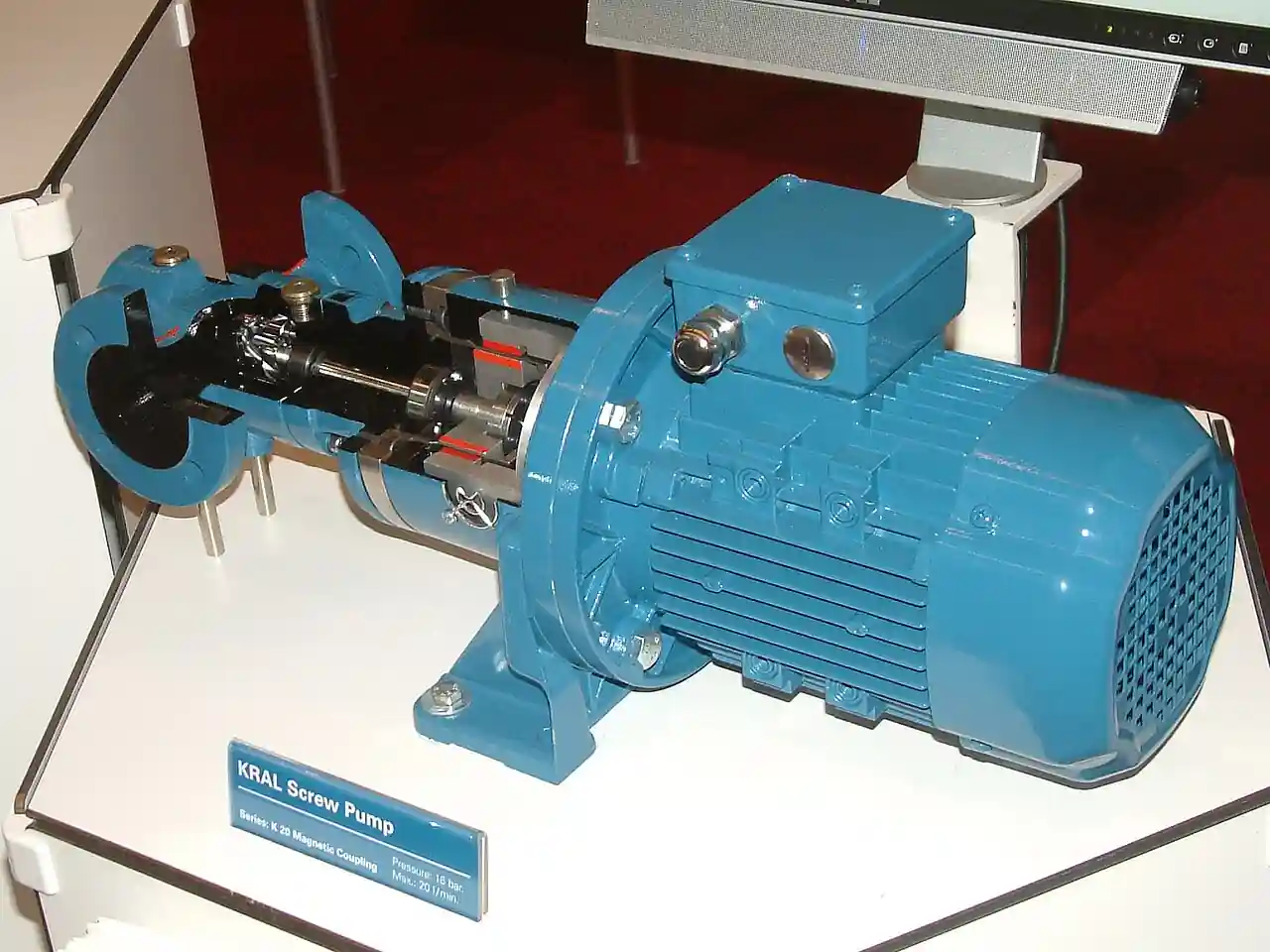
A canned motor pump is a close-coupled, sealless centrifugal pump in which the impeller and the motor rotor share a single shaft inside one welded pressure casing. Liquid enters the suction nozzle, passes through the impeller, and a controlled portion of the discharge is diverted through the motor itself: it flows through the narrow gap between the rotor can and the stator can, lubricates the sleeve bearings along the rotor, and returns to the suction side of the hydraulics or to an external cooling loop. The stator winding sits dry behind a welded can of typically 0.3 to 0.6 mm corrosion resistant alloy, while the rotor runs submerged in the process liquid behind its own sleeve. No shaft penetrates the pressure boundary anywhere, so there is no location for a mechanical seal, and the leak path that defines conventional pumped machinery is designed out rather than managed.
Procurement engineers meet these machines where a leak is not an inconvenience but a reportable event: heat transfer circulation at 250 to 400 deg C, toxic and VOC liquids where fugitive emissions are counted in grams per hour, liquefied gases pumped under vapor pressure such as ammonia, propylene, and refrigerants, and high pressure boiler feed and reactor charge service. The decision this page settles is narrow and practical: whether the duty genuinely requires a canned construction rather than a sealed alternative, which cooling circuit and bearing set survive the liquid, and which protection and monitoring devices must ride along to keep a wet rotor machine alive. The answer lands as an RFQ line set, construction class, can material, circulation scheme, filtration grade, instrumentation, and interlocks, and every chapter below feeds that line set so the machine is bought, not hoped for.
This page treats the canned motor pump as a purchasing object: what the welded cans and the cooling circulation loop demand in real numbers, how API 685 and ASME B73.3 differ as purchasing frames, why sleeve bearings running in process liquid set the solids and dry run limits, and how the whole machine is protected and monitored. It is written for engineers who issue purchase specifications for zero leak duty, not for readers who want a brochure summary.
Chapter 1 / 06
What a Canned Motor Pump Is and What Is Being Decided
The architecture is the definition. A canned motor pump, sometimes called a sealless canned pump or simply a canned pump, integrates the hydraulic end and the electric motor into one welded casing assembly: liquid passes from the suction nozzle through the impeller, a bleed stream carries discharge liquid rearward through the motor gap, and the rotor spins in the process while the stator winding stays dry behind its sleeve. Because the casing is also the motor frame and the pressure boundary, the machine arrives factory aligned. The buyer is purchasing a single pressure vessel with a rotor inside it, and that framing changes how the specification, the installation, and the spare parts strategy must be written.
Two containment boundaries act in series. The pump casing is the first, rated for the full system pressure, and the welded can set is the second, so a failure of one boundary still leaves the liquid enclosed. This dual containment is why process safety reviews accept canned machines indoors on liquids that would otherwise be pushed to remote open air installations. The price of that containment is that the motor, its bearings, and its heat rejection all live inside the hydraulic circuit: the liquid must pump, lubricate, and cool simultaneously, and it must remain clean enough and liquid enough to do all three at once. Every serious datasheet argument on this page traces back to that single trade.
What is actually being decided in this purchase is three layered questions. First, whether the duty genuinely requires a sealless machine: a liquid that is toxic, flammable, vaporizing, or expensive enough that any leak is a reportable event, against a liquid an ordinary centrifugal pump handles with a double mechanical seal and a barrier fluid plan whose annual cost is lower than the canned premium. Second, which construction class fits: API 685 for petroleum and heavy duty process service, ASME B73.3 for chemical duty, or a vendor standard for utility heat transfer loops. Third, which cooling circuit, bearing set, filtration grade, and protection package keep the wet rotor alive, because those accessories, not the impeller, decide the service life.
Against its neighbors the canned machine occupies deliberate ground, and the full tradeoff belongs in the selection chapter. A conventional centrifugal pump with a double mechanical seal and an API 682 plan 53 or 54 barrier system remains the default for ordinary liquids: the seal is a managed leak path, but seal support systems are inexpensive and standard motors can be repaired in any shop. A magnetic drive pump is also sealless and keeps its motor dry in air, transmitting torque through a magnet coupling across one isolation shell, which means one containment boundary instead of two and a motor any electrician can service. At small flows a diaphragm pump or a metering pump delivers zero leak dosing with better flow accuracy than any rotodynamic machine, and for very high pressure reactor charge duty a multistage pump architecture in canned form is a specialized purchase rather than a catalog default.
Four standards organize the datasheet. API 685 is the sealless centrifugal pump standard for petroleum, petrochemical, and gas industry process service, and it imports the discipline of the API 610 world: defined test levels, material traceability, and mandatory monitoring expectations. ASME B73.3 is the specification for sealless horizontal end suction metallic centrifugal pumps for chemical process duty, the purchasing frame for most chemical machines. IEC 60034 governs the motor itself, insulation class and temperature rise, which matters because the winding is cooled by the process. ISO 9906 fixes the hydraulic performance acceptance grades behind the test certificate. Where the area is classified, ATEX or IECEx documentation applies, and the canned construction is often the simplest compliance route because there is no seal to leak. A datasheet that cites none of these is a price tag, not a specification.
The RFQ should name the station, not the machine alone. A canned installation runs with a Y strainer or duplex filter upstream sized to 25 to 50 micrometers, isolation valves that let the filter be serviced, a minimum flow path protected by a check valve where the system curve can close in on the pump, and discharge instrumentation: at minimum a pressure transmitter or a pressure gauge, and a power monitor that trips the machine before the bearings destroy themselves. Writing the whole loop into one purchase order makes one supplier check filtration, hydraulics, and protection compatibility in a single pass.
Chapter 2 / 06
How the Wet Rotor Machine Works
The containment physics start with the cans. The stator can and the rotor can are thin welded sleeves, roughly 0.3 to 0.6 mm wall, of austenitic stainless steel of the 316L class or a nickel alloy for hot and concentrated services. They must be thin because both sleeves sit inside the motor's magnetic air gap: every fraction of a millimetre of sleeve widens the gap and degrades the magnetic circuit. They must also resist the process with essentially zero corrosion allowance, because a wall measured in tenths of a millimetre cannot sacrifice anything. The rotating and stationary fields induce eddy currents in any conductive sleeve they cross, so can alloys are chosen for high electrical resistivity, and even then the can set typically costs 2 to 5 efficiency points against a comparable dry motor centrifugal pump. That standing penalty is the price of zero leak duty.
Cooling and lubrication share one circulation loop. In the standard reverse circulation arrangement, discharge pressure drives a bleed stream from the volute through rear passages into the rotor can gap; the stream flows along the rotor, lubricates each sleeve bearing in turn, and returns to the suction region. The stream carries away the winding heat, can eddy losses, and bearing friction, so its flow rate is fixed by a heat balance: temperature rise multiplied by mass flow must exceed the machine's total losses at the duty point. For heat transfer fluids at 250 to 400 deg C the internal loop cannot reject heat into liquid that hot, so the machine carries an external loop with a heat exchanger that cools the circulated stream before it re-enters the motor. A blocked circulation path, from a blinded strainer or a closed valve, converts the motor into a sealed heater, and windings burn out within minutes on hot service.
The bearings are the honest limit of the machine. Radial support comes from a pair of sleeve bearings, graphite for general chemical duty at moderate temperature, or silicon carbide for hard, hot, clean service, both running directly on the process liquid. Axial load lands on thrust faces or a thrust collar of the same material pairs. None of these combinations tolerates solids: the running films are thin, graphite is soft, and silicon carbide is hard but brittle, so a grain that bridges a bearing clearance scores or shatters the pair. Hence the 25 to 50 micrometer filtration requirement in every canned motor pump manual, enforced by a Y strainer or duplex filter upstream, and the absolute prohibition on dry running: with no external oil supply, a starved bearing pair seizes in seconds.
Axial thrust is handled hydraulically before it reaches those faces. The impeller generates downthrust, and pressure acting on the exposed rotor areas adds an unbalance force that grows with discharge pressure. Self-balancing designs route liquid from behind the impeller through balancing holes or a balancing drum back to suction pressure, so the residual thrust carried by the bearing faces stays small across the flow range. In high pressure multistage pump versions, where two or more impeller stages stack in series inside the same canned envelope, the balancing design becomes the core engineering of the machine, and it is one of the reasons high pressure canned units come from a short list of manufacturers.
Vapor pressure margin is the selection number most often missed. The internal circulation loop sees pressures below discharge, and near the suction return the local pressure approaches suction conditions. If the liquid sits at or near its vapor pressure, as liquefied gases do by definition, flashing inside the can gap collapses the cooling flow and cavitates the bearing pairs from the inside. Vendors therefore require the liquid to arrive with a stated subcooling margin below its boiling point at suction pressure, typically of the order of 3 to 10 deg C or an equivalent pressure margin, and the suction vessel design must guarantee that margin at the worst case summer temperature, not at the design average.
The motor is a standard squirrel cage induction machine in everything except its cooling. Two pole speeds of 2,900 or 3,500 rpm dominate, practical shaft power extends to a few hundred kilowatts, and insulation is class F or H per IEC 60034 with PT100 sensors embedded in the winding as the standard monitoring point. Starting is hard on a wet rotor machine: inrush heats a winding whose only heat sink is the process, so vendors limit consecutive cold starts per hour. A power monitor serves as dry run protection because absorbed power collapses the moment the machine runs dry, and a VFD is acceptable for capacity control provided the internal circulation, which scales with speed, still meets the heat balance at minimum speed, which is why many vendors specify a minimum frequency floor or an auxiliary circulation pump for wide range VFD duty.
Chapter 3 / 06
Types, Construction, and Duty Boundaries
Two code families frame the catalog. API 685 machines are built for petroleum, petrochemical, and gas process duty and inherit the API 610 world's requirements: heavier casings, documented material traceability, certified test curves, and defined monitoring. ASME B73.3 machines are the chemical duty workhorses: dimensional standardization, interchangeable envelope, and a documentation package that fits most acid, caustic, and solvent installations. Both standards cover the two sealless architectures, canned and magnetically coupled, so the code choice and the architecture choice are separate decisions.
Construction variants follow the cooling problem. The standard machine uses reverse circulation and covers most chemical and utility liquids from roughly minus 30 to plus 150 deg C. External loop machines add a heat exchanger, with forced or thermosyphon circulation, and move the envelope to roughly plus 450 deg C for hot oil and heat transfer circuits, with the motor section insulated from the casing heat. Liquefied gas versions for ammonia, propylene, refrigerants, and LNG at minus 162 deg C address the opposite problem: keeping the liquid subcooled as it passes through the motor gap in a casing colder than the surrounding air. High pressure multistage versions stack two to five impeller stages for boiler feed and reactor charge service at several hundred metres of head. The HERMETIC CN and CNF V-line documentation listed in the sources is a representative catalog that shows these variants side by side.
Materials follow the liquid. Casings are CF8M stainless steel as the chemical default, duplex 2205 for chloride rich service, and nickel alloys for hot concentrated acids and alkalis. The can set is 316L class stainless steel as standard, nickel alloy where the process demands it, and the specification should name the alloy because there is no corrosion allowance to hide behind. Bearings split by temperature and cleanliness: graphite sleeves suit general chemical duty and survive marginally dirty liquid better than ceramics, while silicon carbide pairs take clean hot service to their temperature limit. The gasket and O-ring set at the casing joints and the terminal box feedthrough are the quiet specification items: every one is wetted or heat loaded, and a feedthrough failure strands a healthy machine.
The duty boundaries are unforgiving and worth stating bluntly. The liquid must be clean: no machine in this class tolerates solids beyond the 25 to 50 micrometer filtration limit, and services carrying crystals or catalyst fines need a different pump or a dedicated solids handling strategy. The liquid must be present: dry run destroys the bearing set in seconds, so protection is not an accessory. The liquid must lubricate: very low viscosity liquefied gases demand vendor verified bearing designs, and viscous liquids above roughly 100 to 200 centistokes degrade the gap flow and heat balance to the point where a gear pump or another positive displacement machine is the honest answer. And the power ceiling of a few hundred kilowatts means crude transfer mainlines belong to a pipeline pump family built for megawatt duty.
The duty map below consolidates the boundaries into one table a specifier can scan before writing the RFQ.
Service
Suitable construction
Construction to avoid
Heat transfer fluid circulation at 250 to 400 deg C
External cooling loop, class H insulation, nickel alloy cans
Standard reverse circulation machine (internal loop cannot reject heat)
Toxic or VOC liquid transfer under emissions permit
API 685 canned machine with dual containment and monitoring ports
Single mechanical seal pump chosen on barrier plan cost alone
Ammonia or propylene transfer under vapor pressure
Liquefied gas construction, subcooling margin 3 to 10 deg C confirmed
Standard machine with no vapor pressure margin check
High pressure boiler feed or reactor charge
Multistage canned machine with balancing drum and external loop
Single stage machine pushed beyond its head class
Clean chemical transfer at moderate conditions
ASME B73.3 standard machine, reverse circulation
High temperature variant paid for and never used
Liquid carrying crystals or catalyst fines
Not this machine; specify solids handling or heavier filtration
The table below decodes the datasheet lines that decide whether a quoted machine matches the service; the paragraphs after it explain what to demand and what a weak answer looks like.
Attribute
Typical range or options
What it decides
Duty flow
1 to 600 m3/h catalog range, larger custom
Hydraulic size, nozzle rating, and circulation driving head
Differential head
Single stage to about 100 m; multistage beyond 400 m
Stage count and the balancing design behind it
Motor power
1 kW to a few hundred kW
Heat balance load, starter, and start frequency limit
Liquid temperature
Minus 162 to plus 450 deg C by variant
Can alloy, insulation class, cooling scheme
Casing pressure rating
PN16 to PN40 common, higher by special design
Casing class and the differential across the can set
Can set
316L class or nickel alloy, 0.3 to 0.6 mm welded
Corrosion life and second containment integrity
Bearings
Graphite or silicon carbide sleeves plus hard thrust faces
Solids tolerance and temperature limit
Cooling circuit
Reverse circulation or external heat exchanger loop
Heat rejection at the duty point and at turndown
Filtration requirement
25 to 50 micrometers upstream
Y strainer or duplex filter sizing in the same order
Monitoring package
Winding PT100s, power monitor, circulation flow indication
Protection against dry run and loop blockage
The cooling circuit row is where quotations go vague, so make it numeric. Ask for the required circulation flow and the expected temperature rise through the motor at the duty point, and check both at minimum continuous flow, where discharge differential is lowest. A machine that meets its heat balance only at best efficiency point will cook its winding every time the system demands turndown. Where the loop is external, the heat exchanger duty, the circulated flow rate, and the failure behavior of the circulation pump belong on the datasheet, and the control chain, a flow meter or flow switch, a temperature transmitter, and the trip logic into the PLC, belongs in the RFQ scope rather than a later controls package.
The can row deserves the same rigor. A 0.3 to 0.6 mm sleeve has no corrosion allowance, so the specification should state the alloy, the expected corrosion rate, and the inspection evidence at manufacture: weld records and nondestructive examination of the can seams. For chloride service, duplex 2205 or a nickel alloy is not an upgrade to defer, because a perforated stator can means process liquid in the winding and a machine that is usually a total loss. Ask vendors for can velocity limits as well, since erosion thins sleeves exactly where corrosion does, and ask how can integrity is monitored in service.
The variant table below compresses the construction decision into the form a specifier can defend in a review meeting.
Construction variant
Cooling method
Temperature class
Typical service
Standard reverse circulation
Internal discharge bleed through the can gap
Minus 30 to plus 150 deg C class
Chemicals, water, clean solvents
External heat exchanger loop
Closed loop with cooler, forced or thermosyphon
To plus 450 deg C with insulation
Heat transfer fluids, hot oil
Liquefied gas construction
Subcooled liquid through the gap, vent provisions
Minus 162 to plus 40 deg C
Ammonia, propylene, refrigerants, LNG
Multistage high pressure
Reverse or external, with balancing drum
To plus 300 deg C class
Boiler feed, reactor charge
Name the variant in the RFQ: it determines nozzle count, external piping, insulation scope, and the instrument list long before price appears, and two quotations that differ only in construction variant are not comparable line items. Where the duty sits between variants, for example a heat transfer loop at 180 deg C, state the temperature honestly, let both be quoted, and compare instrument lists and heat balances rather than headline prices.
Chapter 5 / 06
Selection Decision Factors and RFQ Language
The decision sequence is short enough to run as a checklist in a specification meeting, and each step eliminates a class of quotations before price comparisons begin.
Confirm the duty genuinely requires sealless construction: toxicity, emission permit limits, product loss value, and insurance or process safety requirements, all stated in the RFQ so the premium is justified on paper.
Write the liquid honestly: chemistry, temperature range, vapor pressure or subcooling, viscosity, solids content, and entrained gas, because these select can alloy, bearings, and cooling variant in one pass.
Fix the vapor pressure margin: state the minimum subcooling at worst case temperature and require vendor confirmation of the internal loop's lowest pressure point.
Choose the construction class, API 685 or ASME B73.3, and the construction variant from the chapter 4 table, by name, never by vendor default.
Specify the circulation scheme with numbers: required flow, temperature rise through the motor, and behavior at minimum continuous flow.
Define filtration and commit to the hardware: 25 to 50 micrometers, duplex filter or Y strainer with differential indication, purchased in the same order as the machine.
Package the protection: winding PT100s, power monitor for dry run, low flow and circulation loss trips, and the PLC logic that ties them together with vendor confirmed setpoints.
Fix the verification evidence: certified performance test to ISO 9906, can weld examination records, insulation resistance baseline, and material certificates EN 10204 3.1.
Against the magnetic drive pump, the other sealless architecture, the choice runs as follows, and it belongs here in the selection chapter. Both eliminate the mechanical seal, and both leak only if a static boundary fails. The magnetic drive pump keeps a conventional dry motor in air: any electrician can rewind it, and a failed motor does not scrap the hydraulics, while a canned winding repair is factory work that can cross an ocean. Its isolation shell is a single containment boundary where the canned machine carries two. Magnet couplings impose their own limits: they decouple under overload, and magnet temperature ceilings complicate hot service, while the canned machine's thermal ceiling is only its insulation and cooling loop. Canned machines are usually the stronger answer for liquefied gases, where the submerged motor tolerates the cold and the subcooling margin protects both winding and bearings, for high temperature loops with external cooling, and for installations with no room to align a separate motor. Magnetic drive usually wins where motor serviceability and interchangeability with the plant's sealed pump fleet dominate the maintenance strategy. Choose against the service, not against the catalog that arrived first.
The remaining neighbors own the edges of the map. For dosing a few hundred liters per hour at one percent accuracy, a metering pump is the correct instrument, and its diaphragm construction is legitimately zero leak. For liquids carrying solids or slurries at moderate pressure, an air operated or hydraulic diaphragm pump tolerates what no wet rotor machine will. For viscous clean liquids, a gear pump moves fluid the canned gap cannot lubricate. Where the only problem is air in the suction line at startup after maintenance, a self priming pump or a priming eductor driven by a small vacuum pump solves it for a fraction of a sealless premium. For crude and product transfer along trunk lines at megawatt scale, a dedicated pipeline pump family exists and no canned machine competes.
Instrument the machine as part of the purchase. The chain that keeps a canned machine alive is short: a discharge pressure transmitter or at least a pressure gauge, winding PT100s read into the motor protection relay, a power monitor for dry run and rotor drag, and on external loop machines a flow meter or flow switch on the circulated stream with a temperature transmitter on the return. The trip logic lands in the plant PLC or in the relay itself, but the setpoints belong in the RFQ so the vendor confirms them against real limits. Where the machine runs on a VFD, the minimum frequency floor from chapter 2 becomes a control specification line, not a startup discovery, and the Y strainer or duplex filter differential alarm belongs on the same instrument list.
The application map below turns the selection logic into a table the project file can carry.
Application
Construction to specify
Check before order
Heat transfer circuit at 320 deg C
External loop, class H insulation, nickel alloy cans
Heat exchanger duty and loop failure behavior
Toxic chemical transfer in an API 685 plant
Dual containment with leak monitoring ports
Containment monitoring scope in the instrument list
Ammonia or propylene loading
Liquefied gas variant, subcooling margin confirmed
Worst case summer suction temperature
High pressure boiler feed
Multistage canned machine with balancing drum
Thrust balance across the full flow range
Refrigerant circulation at minus 30 deg C
Cold service construction with dry gas vent
Moisture exclusion at the terminal box
Clean solvent transfer at moderate duty
Standard ASME B73.3 reverse circulation
Filtration hardware purchased in the same order
The RFQ block should be written once and reused. A complete block reads: quantity, flow, and head at normal and rated conditions; liquid chemistry with temperature range, vapor pressure or subcooling, viscosity, and solids; construction class and variant by name; can alloy and thickness with weld examination evidence; bearing materials; circulation scheme with required flow and temperature rise; filtration grade and hardware; casing rating and allowable nozzle loads; motor data, insulation class, PT100 count, and start limit; protection package, power monitor, low flow, circulation loss, and trips with setpoints; VFD applicability and minimum speed; and certificates, performance test to ISO 9906, material certificates EN 10204 3.1, and ATEX or IECEx where the area is classified. A quotation returned without the heat balance or the can weld records is incomplete at any price.
Chapter 6 / 06
Installation, Standards, Failure Modes, and Maintenance
Installation is piping discipline. The machine arrives aligned by construction, close coupled with no coupling to align, so the two remaining threats are nozzle loads and dirt. Support piping independently so flange loads stay inside the vendor limits, because a canned casing is also the motor frame and piping strain distorts the can gap and the bearing bores. Fit the Y strainer or duplex filter upstream with a differential gauge so blinding is visible before the circulation loop starves. Provide a minimum flow line with a check valve and an orifice when the system can run the pump at shutoff, and isolate with a full bore valve, a ball valve at small bore or a gate valve at large bore, so the machine can be locked out without fighting a throttling element.
Commissioning protects the bearings and the winding. Flush the suction piping to bore cleanliness before the first start, because construction debris does most of the bearing damage a canned machine ever sees and the strainer only catches what reaches it. Unlike a self priming pump, a wet rotor machine cannot clear its own suction, so fill and vent the casing before any start, confirm the circulation loop is flowing, and where the suction system needs initial evacuation use a temporary vacuum pump rather than dry bumping the motor. Prove the interlocks by test, not by faith: dry run trip on power collapse, low flow trip, and circulation loss where fitted. Then record the operating fingerprint, current, winding temperatures, and casing vibration at three flows, because every future condition judgment is made against this baseline.
The standards set the verification frame. API 685 and ASME B73.3 define the machine scope and its documentation. ISO 9906 fixes the hydraulic acceptance grades quoted on the test certificate. IEC 60034 governs the winding's insulation class and temperature rise, and the embedded PT100s make that class observable in service. ATEX or IECEx documentation applies in classified areas. One standard marks the alternative: API 682 defines the mechanical seal plans that a sealless purchase avoids, and writing the barrier system's cost and consumption against the canned premium into the project file keeps the zero leak decision defensible at the next budget review.
Failure modes in service follow a short and predictable list. Bearing wear from solids is first: a filtration lapse or a strainer bypassed during commissioning scores graphite sleeves or chips silicon carbide, shows up as rising vibration and falling performance, and ends in rotor seizure if ignored. Loss of circulation is second and faster: a blocked filter or a closed valve stops heat rejection, and winding temperature climbs to trip or burnout within minutes on hot service. Can corrosion or erosion is third and quietest: a thinned or perforated sleeve lets process into the winding space, detected by insulation resistance monitoring or a moisture sensor, and usually means a machine replacement rather than a repair. Winding burnout from blocked circulation closes the list, together with thermal shock on hot oil machines and moisture ingress at the terminal box on cold service machines.
Maintenance is trending, not overhaul. Track winding PT100 readings against the commissioning baseline, insulation resistance quarterly, filter differential daily in dirty service, and casing vibration monthly. Clean the strainer on schedule rather than on trip. At major intervals, an internal inspection checks can thickness, bearing clearance, and thrust face condition; anything deeper goes back to the factory or an authorized shop, which is why critical services keep a spare machine. None of these routines costs a tenth of one unplanned stop, and each produces numbers the next RFQ can use.
FAQ
What is the difference between a canned motor pump and a magnetic drive pump?
Both are sealless, with no mechanical seal anywhere. A canned motor pump integrates the motor inside the pressure casing: the rotor runs submerged in the pumped liquid behind two thin welded cans, giving two containment boundaries and factory-only winding repairs. A magnetic drive pump keeps a conventional dry motor in air and transmits torque through a magnet coupling across a single isolation shell, so the motor is field serviceable with one containment boundary. Canned suits liquefied gases and hot cooling loops; magnetic drive suits plants that prize motor serviceability.
Can a canned motor pump run dry?
No, and the failure is measured in seconds. The sleeve bearings and thrust faces are lubricated exclusively by the pumped liquid, and the winding is cooled by the internal circulation stream, so a dry start or lost suction starves both at once. Protection is mandatory: a power monitor trips within moments of the power collapse that accompanies dry running, and a low flow or level based trip backs it up. If dry running is credible, buy the protection with the pump and prove the trip by test.
What filtration does a canned motor pump need?
Plan on 25 to 50 micrometers upstream of the machine, enforced by a Y strainer or a duplex filter with differential pressure indication. The bearing films are thin, graphite sleeves are soft, and silicon carbide is hard but brittle, so grit that a sealed pump would shrug off destroys a wet rotor bearing set. The filter is part of the pump specification, not site standard piping. Services that cannot meet the cleanliness limit, such as liquids carrying crystals or catalyst fines, belong to a different pump family.
What temperatures can it handle?
Standard reverse circulation machines cover roughly minus 30 to plus 150 deg C on clean liquids. External cooling loop constructions with heat exchangers and insulation extend heat transfer service to about 450 deg C, and liquefied gas versions run down to minus 162 deg C for LNG. The limits are set by the insulation system, the can alloy, and the gasket set, not by the hydraulics, so the temperature class must be named in the RFQ by variant and the winding PT100 alarm setpoints confirmed against it.
How is a canned motor pump monitored and protected?
The standard package is a set of PT100 sensors embedded in the winding, a power monitor on the starter that detects dry run and rotor drag from absorbed power, and on external loop machines a flow meter or flow switch plus a temperature transmitter on the circulated stream. Trip logic lands in the motor protection relay or the plant PLC. Setpoints come from the vendor's heat balance and belong in the RFQ, and commissioning proves each trip by test rather than by trusting the drawing.
API 685 or ASME B73.3, which standard applies?
API 685 is the sealless standard for petroleum, petrochemical, and gas process service: heavier duty casings, material traceability, certified testing, and mandatory monitoring expectations, essentially API 610 discipline applied to sealless machines. ASME B73.3 is the specification for horizontal end suction sealless metallic centrifugal pumps in general chemical duty, with standardized dimensions and a lighter documentation package. A refinery toxic service normally carries API 685, a chemical plant acid transfer normally carries B73.3, and both standards cover canned and magnetically coupled architectures.
What is the vapor pressure margin and why does it matter?
For liquids pumped at their vapor pressure, such as ammonia, propylene, or refrigerants, the liquid must arrive subcooled, typically by 3 to 10 deg C or an equivalent pressure margin, so it cannot flash as it passes through the motor gap at local pressures below discharge. Flashing in the gap collapses the cooling circulation and cavitates the bearing pairs, destroying the machine from the inside. The margin is set by the suction vessel's pressure and worst case temperature, so it must be confirmed for summer conditions, not design averages.