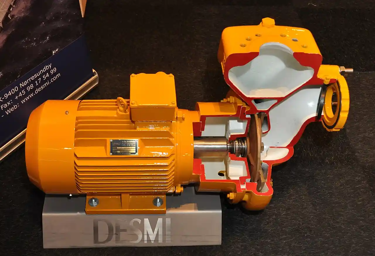
An axial flow pump is a rotodynamic machine whose impeller is a propeller running in a bowl or pipe, so that water enters and leaves parallel to the shaft axis rather than being turned radially outward into a volute. It is the high specific speed end of the pump family, above roughly 160 in the European nq convention, and that single number explains everything about its duty: flows from 0.2 to 30 m3/s at heads of 1 to 12 m per stage, the territory of flood control and drainage, circulating water for power plants and HVAC, irrigation lift, and large process transfer. Styles divide by installation: vertical wet pit machines suspended in an open sump on a column with the discharge elbow above deck, dry pit elbow and angle discharge versions, tube or riser in-line machines mounted inside the piping itself, submersible propeller pumps set directly in the channel, and portable diesel driven flood sets. Bowls are cast iron with bronze or stainless propellers in fresh water and duplex grades in seawater; motors are vertical hollow shaft IEC 60034 machines on the wet pit style and sealed submersible motors with dual mechanical seal protection below.
Procurement engineers meet these pumps on drainage and stormwater stations, on cooling water and condenser circuits, on irrigation heads and canal lift, and on treated wastewater return. The decision this page settles is narrow and practical: whether the duty genuinely belongs to a propeller machine rather than a radial one, which style fits the civil works, what submergence and sump geometry the inlet needs, and what construction, driver, screen, discharge arrangement, and test evidence the RFQ must state. The answer lands as a line set: duty point, sump dimensions and submergence, style, materials, motor rating and type, inlet screen, discharge elbow, and acceptance test to ISO 9906. Every chapter below feeds that line set so the station is bought, not hoped for.
This page treats the axial flow pump as a purchasing object: what propeller hydraulics and specific speed actually imply for flow and head, how vertical wet pit, elbow, tube, and submersible styles trade civil works against mechanical risk, what submergence and sump practice per Hydraulic Institute guidance the inlet demands, and how style, materials, driver, and test grade combine into a defensible RFQ. It is written for engineers who issue purchase specifications for high flow low head stations, not for readers who want a brochure summary.
Chapter 1 / 06
What an Axial Flow Pump Is and What Is Being Decided
The geometry is the definition. In a radial machine, water enters on the axis, turns 90 degrees through the impeller passages, and leaves at the periphery into a spiral volute, converting the impeller's momentum in one step. In an axial flow pump, the impeller is a propeller with a small number of blades, two to six by design, and the water passes through those blades without ever leaving the shaft axis: a short inlet bell straightens the approach, the propeller adds head by blade lift, and a set of stationary guide vanes in the bowl recovers the swirl as pressure before the column or discharge pipe. The consequence is a machine that moves enormous volumes against small lifts: one meter of head at 10 m3/s is routine axial work, and the same duty would demand an inefficient, throttling-prone radial impeller of absurd diameter. A regenerative turbine pump or a small high head centrifugal pump is the exact opposite corner of the same family map, tens of bars from a few cubic meters per hour.
What is actually being decided in this purchase is a station, not a widget. The RFQ fixes the duty point, flow and total head at the rated condition; the sump interface, dimensions, and minimum submergence that decide whether the inlet vortices and cavitates; the style, vertical wet pit, dry pit elbow, tube in-line, or submersible propeller, which is mostly a decision about civil works and maintenance access; the materials by water class from cast iron and bronze to duplex; the driver, a vertical hollow shaft motor on the structure or a sealed submersible motor in the flow; the inlet screen that keeps rope and rag off the propeller; the discharge arrangement including elbow angle and siphon provisions; and the acceptance test grade per ISO 9906. Each item is a chapter section below, and each lands as a numbered line in the purchase specification.
The boundary against the neighbors is worth one plain paragraph before the detail. The generic centrifugal pump, radial flow with a volute, owns the higher head lower flow middle of the map: above roughly 12 m per stage, a radial or mixed flow impeller does the work better. Deep settings and higher heads stack many stages, and that deep well architecture is the vertical turbine pump, which is the multistage pump answer when the lift exceeds what one or two propeller stages give. Between the radial and axial ends sits the mixed flow impeller, and honest selection treats the whole range as a continuum: many manufacturers offer the same wet pit column with radial, mixed, or axial stage types selected by the duty point, which is why the RFQ should state the duty and not the family guess. On the solids side, a sewage pump with channel or vortex impellers handles raw wastewater that would wrap a propeller, and a slurry pump with hardened metal or rubber wetted parts takes abrasive grit that would sandblast blade edges away in weeks. This page stays with the clean and stormwater end of that map, where the propeller earns its efficiency.
Three standards organize the datasheet. Hydraulic Institute guidance, above all ANSI/HI 9.8 on pump intake design, fixes how sumps are dimensioned against bell diameter and flow so the inlet receives uniform, swirl free, vortex free flow, and its minimum submergence figures are the difference between a quiet machine and an eroding one. ISO 9906 fixes the hydraulic performance acceptance test framework and grades, and the grade, commonly 2B for these machines, belongs in the RFQ with witness points. IEC 60034 governs the motors on every style. A datasheet that quotes none of the three is a price tag, not a specification.
The RFQ should also name the station around the pump. Downstream, a low slam check valve or a protected isolation scheme keeps the water column from returning through the propeller on trip, and the choice among a swing check valve, a tilting disc check valve, or an axial nozzle pattern is a purchase decision of its own. Large line isolation on these stations is usually a butterfly valve for diameter economics or a gate valve on smaller headers. Small auxiliary takeoffs, sealing and flushing water for the shaft bearings on dry pit machines, deserve a Y strainer so that the same sand the sump lets through does not settle in the smallest passages on the unit. Stating the station rather than the pump lets one supplier check the whole hydraulic chain in a single pass instead of five arguments at commissioning.
Chapter 2 / 06
How the Propeller Moves Water
The propeller blade is an airfoil in water. As it rotates, each blade section sees a relative velocity made of the forward axial flow and the blade's own tangential speed, and generates lift along the passage, adding energy to the flow as a pressure rise across the stage. Because the flow stays axial, the stage's specific speed is the highest in the rotodynamic family, above roughly 160 in the European nq convention that divides radial, mixed, and axial duty, and that number is what lets one propeller stage move 0.2 to 30 m3/s against 1 to 12 m of head at speeds in the 300 to 1,500 rpm family band on 50 and 60 Hz supplies. Behind the propeller, the stationary guide vanes in the bowl de-rotate the swirl the blades leave behind and convert it to static pressure, and in a multistage stack the next propeller sits immediately downstream, which is why bowl assemblies, not volutes, are the building blocks of this family.
The performance curve shape is the most purchase-relevant physics on the page. Head rises steeply as flow falls toward shutoff, and so does shaft power: an axial flow pump draws the most power at closed valve, the exact opposite of a radial machine whose power peaks at runout. Two rules follow directly. Never start an axial flow pump against a closed or heavily throttled discharge, because the motor sees near maximum load while producing nothing, and never size the motor on the duty point alone: the motor must carry the curve, including the high power region between shutoff and BEP that flood stations traverse at every start. A mixed flow impeller softens both behaviors, which is one reason the continuum statement in chapter 1 matters at selection.
Efficiency is the family's justification. Large clean water propeller machines reach hydraulic efficiencies in the 80 to 88 percent class, several points above what a radial impeller can deliver at the same specific speed duty, and the best efficiency point is a real target: operation far to either side of it costs efficiency and, beyond roughly 120 percent of BEP flow on many designs, reverses the axial hydraulic thrust upward. That upthrust zone is why manufacturers publish a maximum flow line on their curves and why motor bearings on vertical machines are sized with the whole curve in mind, a point developed with the failure modes in chapter 6.
The suction side governs everything about installation. The machine itself has modest NPSH demand at low heads, but the inlet bell must be submerged deep enough in the sump that neither a free surface vortex nor a subsurface vortex forms: the vortex pulls air into the blades, and aerated flow costs head, destabilizes the motor load, and adds cavitation noise immediately. Hydraulic Institute intake practice dimension sumps against the bell diameter and the flow, sets minimum submergence as a function of both, and dictates floor clearances, corner fillets, and approach velocities. Where civil works cannot honor the tables, the engineered answers are curtain walls, splitters, and cones in the sump, or a longer, more forgiving wet well, and none of them can be bought after the concrete has cured.
On the discharge side the geometry completes the duty. Wet pit machines lift the water through the column to an elbow above deck, commonly a 60 or 90 degree bend, where a high point can form: a siphon arrangement with an air release valve at the crest recovers some static lift on tall discharges, and a siphon breaker or vacuum breaking valve admits air on stop so the returning column cannot spin the propeller backwards. Tube and riser in-line machines have no sump at all: the propeller bowl sits inside the pipeline like a valve, and the motor is either a dry mounted unit on a long shaft or a submersible motor folded into the tube. Every one of these choices changes the civil interface, which is why the style decision belongs at the top of the RFQ, not the end.
Chapter 3 / 06
Types, Construction, and Duty Boundaries
The vertical wet pit style is the reference architecture and the Flowserve AFV family in the sources is its shape: a bowls assembly with propeller and guide vanes at the bottom, a column that carries both the rising water and the line shaft, a discharge elbow at deck level, and a vertical motor, typically a VHS vertical hollow shaft machine, mounted on the structure above with the pump shaft hanging through its rotor bore and the thrust carried in the motor bearing. Pullout designs let the bowls and shaft be drawn up through the discharge without unbolting the column, a maintenance decision worth real money on stations that cannot be drained; non-pullout designs are simpler and cheaper, and the choice belongs in the RFQ by name. The submersible pump alternative suspends the whole motor on guide rails in the wet well: no structure, no line shaft, and a crane hook replaces a crew.
Dry pit and elbow styles move the machine out of the sump. An angle or elbow discharge pump sits in a dry well beside the wet well, taking suction through a short run and discharging through its casing elbow, with the shaft passing through a stuffing box or a mechanical seal where it leaves the casing. Axially split casings in the CAHR pattern lift the top half for internal access without disturbing the piping, which on a circulating water station means an overhaul without cutting concrete or large bore spools. Tube or riser in-line machines are the same hydraulics packaged inside the pipe itself for HVAC and transfer duty where no sump exists. At the portable end, diesel driven flood sets package a bowl or mixed flow hydraulic end with an engine and a vacuum priming arrangement, and many use self-priming pump style casings because the flood duty rarely offers a designed sump.
The submersible propeller style, the ABS VUPX pattern in the sources, puts a sealed motor in direct contact with the channel: air or oil filled, cooled by the surrounding flow, driving the propeller on a short overhung shaft, and deployed on a guide rail with a duckfoot bend so the unit lifts out without dewatering. Its integrity lives in its sealing: a dual mechanical seal arrangement with an oil filled interstage chamber and a moisture or leakage probe wired to the control panel, so that the first seal failure is an alarm rather than a drowned motor. These units handle stormwater and treated wastewater with modest soft solids, which is exactly the gap between clean water propellers and the rag handling duty of a channel impeller sewage pump.
Construction across the family is compact and standardized. Propellers are cast bronze or stainless steel, 300 series standard, with blades either fixed at manufacture or, in some designs, adjustable at rest, meaning the pitch can be reset at a strip down to shift the curve a few percent when the system behaves differently than the model promised. Bowls and columns are cast iron in fresh water, epoxy coated as standard hygiene practice; seawater and brackish stations move to duplex 2205 or super duplex wetted parts; shafts run in stainless with protective sleeves at every bearing. Line shaft bearings are water lubricated cutless rubber in the column or grease lubricated bronze on dry mounted shafts, and the sleeve-to-bearing clearance is the wear item that governs vibration as the machine ages.
Duty boundaries keep the purchase honest. The axial machine is not a solids machine: rags wrap the propeller hub, and grit sands blades and bearings, so raw sewage belongs to the sewage pump families and abrasive slurry to a slurry pump, and only screened stormwater and clean service water belong here. It is not a high head machine: above roughly 12 m per stage, physics pushes selection toward mixed flow or radial stages, and the honest answer to a deeper lift is a vertical turbine pump stack. It is not self-priming in the way the portable sets are: a wet pit propeller must be submerged, and a dry pit unit needs flooded suction or priming provision. And it is not a throttling machine: efficiency dies quickly off the propeller's band, and flow control belongs to speed, not to a valve pinching the discharge.
The table below compresses the style decision into the form a specifier can carry into a review meeting.
Style
Installation shape
Best duty
Watch items
Vertical wet pit, pullout
Column in open sump, VHS motor on structure, bowls drawn upward for service
Drainage, circulating water, irrigation lift
Structure cost; submergence and sump discipline per HI practice
Vertical wet pit, non-pullout
Column in sump, fixed assembly
Budget stations with dewaterable sumps
Major service means dewatering or divers
Dry pit elbow, axially split
Dry well machine with casing elbow, split cover
Power plant circulating water at scale
Civil cost of the dry well; seal or packing service
Tube or riser in-line
Bowl inside the pipeline, no sump
HVAC and transfer headers
Access planning; motor removal clearances
Submersible propeller
Sealed motor in channel on guide rails
Stormwater, flood cells, treated effluent
Seal and leakage probe integrity; screen discipline
Portable diesel flood set
Skid mounted engine and hydraulic end with priming
Emergency and mobile flood duty
No designed sump; match expectations to hydraulics
Chapter 4 / 06
Key Specification Parameters
The datasheet rows below decide whether a quoted machine matches the station; values are stated as the common industrial span across the maker catalogs behind the sources, with every row confirmed against the specific datasheet before order.
Attribute
Typical range or options
What it decides
Rated flow
0.2 to 30 m3/s by family, duty point stated with tolerance
Sump sizing, column diameter, and screen selection
Total head
1 to 12 m per stage; two stages for the top of the band
Stage count and the axial to mixed flow boundary
Speed
300 to 1,500 rpm family band on 50 and 60 Hz supplies
Civil works, maintenance access, and motor environment
Propeller
Bronze or stainless, fixed pitch or adjustable at rest
Curve shape and the option to trim by pitch at overhaul
Materials by water class
Cast iron and bronze, 300 series, duplex 2205 for seawater
Corrosion allowance and coating specification
Driver
IEC 60034 VHS motor on structure, or sealed submersible motor
Thrust carrying, cabling, and maintenance model
Submergence
Minimum per HI intake practice, stated at lowest sump level
Vortex and cavitation behavior at the inlet bell
Acceptance test
ISO 9906 hydraulic test with grade stated, commonly 2B
Proof of the curve the purchase is priced against
The head row deserves a paragraph of caution because it is where the family boundary bites. Propeller stages live between 1 and 12 m: below about 1 m the machine is almost a stirrer with a motor attached, and above 12 m the efficiency of a pure axial stage collapses while a mixed flow stage takes over gracefully, then a radial stage, then multiple stages. When a buyer asks a propeller for 15 or 20 m, the honest quotation comes back with a mixed flow impeller or a stacked machine, and the RFQ should leave room for that answer rather than hard-coding one impeller type. The materials table below pairs the water class with the wetted parts that survive it.
Water class
Bowls and column
Propeller and shaft
Notes
Clean fresh water
Cast iron, epoxy coated
Bronze or 300 series stainless, sleeved
Commodity construction, best delivery times
Stormwater, screened
Cast iron, epoxy coated, generous wear allowance
Stainless with coated hubs
Screen discipline decides the maintenance interval
Treated effluent
Cast iron or 300 series
300 series stainless
Submersible style with leakage probe standard
Brackish and seawater
Duplex 2205 or super duplex
Duplex with cathodic attention
Material certificates and coating spec in the RFQ
Abrasive laden
Hard faced or coated, replaceable wear parts
Coated blades with sacrificial edges
Consider whether duty really belongs to a slurry family
The driver row closes the purchase. On wet pit structures the VHS vertical hollow shaft motor carries the pump's entire axial thrust, downthrust at normal duty and the upthrust transient beyond BEP flow, and its bearing bracket must be rated for both directions with margin. Non-reverse ratchets stop the column backspinning on siphon break or check valve failure. On submersible units the motor specification shifts to insulation class, duty rating under frequent starts, and the integrity of the cable gland and the dual mechanical seal with its oil chamber probe. In both cases the motor sizing must trace the whole curve per chapter 2, not the single duty point, and the quotation should say so in writing.
Chapter 5 / 06
Selection Decision Factors and RFQ Language
The selection sequence runs as a checklist, and each line eliminates a class of mistakes before the purchase order exists.
Fix the duty point honestly: rated flow, total head at rated and at worst sump level, and the flow range the station must live with across seasons.
Place the duty on the family map: below about 12 m per stage with large flows earns a propeller, deeper lifts shift to mixed flow, then radial, then a staged vertical turbine pump.
Choose the style from the civil works: wet pit column with structure, dry pit elbow with a dry well, tube in-line inside the pipe, or submersible propeller on rails.
Dimension the sump with Hydraulic Institute intake practice: bell submergence at lowest water, floor and wall clearances, approach velocity, and vortex controls.
Set materials by water class per chapter 4, including coatings and wear allowances for grit and screening quality.
Specify the driver across the whole curve: motor rating with the shutoff to runout power band, thrust capability both directions, VHS or submersible.
Engineer the station appurtenances: screens, low slam check valve, isolation, siphon and air valves, sealing water with its own strainer.
Fix the evidence: ISO 9906 acceptance test with grade and witness points, material certificates, and the vibration acceptance at duty.
Against the neighboring pump families, the choice deserves one honest paragraph, and it belongs here in the selection chapter. The generic centrifugal pump, radial with a volute, owns moderate flows at moderate to high heads and loses efficiency at the massive flows and single digit lifts where the propeller lives. The vertical turbine pump stacks mixed or radial stages in a column for deep wet wells and higher lifts, effectively the multistage pump architecture of the same column and motor world, and it is the answer when head per stage climbs beyond propeller territory. A sewage pump with channel impellers takes raw ragged wastewater; a slurry pump in hard metal or rubber takes abrasive grit; both reject propeller geometry for good reasons. Governed fire pump duty under listing rules is bought from listed families, and the axial machine appears in that world only as raw water transfer to a storage, never as the listed unit itself. Where no sump can be built, a self-priming pump or vacuum primed set serves the portable and remote duty, and where a pit exists but no superstructure can be justified, the rail mounted submersible pump families take the load with the motor in the wet. At the small high head corner, a regenerative turbine pump or a magnetic drive pump on sealed chemical duty plays roles the propeller cannot. Selection is the act of placing the duty point on this map and buying the family that owns it.
Station practice on the discharge side rewards a paragraph of its own. These machines move columns of water with real inertia, so the check valve after them must close without slam: a swing check valve with lever and weight or spring restraint, a tilting disc check valve with its fast low-slam disc, or an axial nozzle pattern valve are the three credible answers at these diameters, and the choice is made against the column length and the trip scenario. Isolation on large headers is nearly always a butterfly valve for diameter economics, with a gate valve preferred on smaller headers where bubble tight isolation under seating wears less. The discharge high point takes an air release valve, and the siphon arrangement, where used, takes a breaker on stop. Every one of these items interacts with the pump curve, and every one of them belongs in the same RFQ so one hydraulic party owns the station behavior.
The application map below turns the practice into a table the project file can carry.
Application
Construction to specify
Check before order
Stormwater drainage station
Wet pit or submersible propeller, screened inlet, low slam discharge valve
Submergence at lowest level; screen and rag loading; start frequency
Power plant circulating water
Dry pit axially split elbow machine or large wet pit column
Two-stage need at top of head band; condenser tube erosion limits
HVAC chilled and condenser water
Tube or riser in-line machines in the piping
Access clearances; motor removal path; vibration isolation
Irrigation canal lift
Wet pit column with VHS motor, fixed pitch propeller
Seasonal level range against submergence table; sand load
Treated effluent return
Submersible propeller with leakage probe and rail lift
Soft solids tolerance; seal alarm wiring; coating spec
Emergency mobile flood duty
Diesel driven portable set with priming, screened suction basket
Realistic suction lift; fuel logistics; hose head loss in the duty point
The RFQ block should be written once and reused. A complete block reads: quantity and standby philosophy; rated flow and total head with sump level range; water analysis and solids or screening statement; style by name including pullout or non-pullout; stage count and propeller pitch provision; materials by water class with coating specification; motor rating, type, insulation, thrust capability across the curve, and IEC 60034 conformity; sump dimensions and the required minimum submergence shown against them; inlet screen type and bar spacing; discharge elbow angle, siphon and air valve provisions; the check valve and isolation scheme with the trip scenario stated; acceptance test per ISO 9906 with grade and witness points; material certificates; and the spares list, wear parts, sleeves, bearings, and one propeller set for critical stations, priced at order. A quotation returned without the curve band between shutoff and runout, or without a submergence statement, is incomplete at any price.
Chapter 6 / 06
Installation, Standards, Failure Modes, and Maintenance
Installation quality decides whether the hydraulics ever meet their test curve. Set the bowls in a sump dimensioned to Hydraulic Institute intake practice: bell submergence honored at the lowest operating level, floor clearance and wall clearances per the tables, approach flow straightened over the last several diameters, and anti-vortex provisions, splitters, fillets, or curtain walls, where the civil geometry cannot be changed. Fit and keep the inlet screen, because rope, rag, and plastic film wrap a propeller hub in minutes and the resulting imbalance destroys line shaft bearings far faster than any hydraulic fault. Verify column plumb and motor alignment on wet pit structures, since a tilted column loads every intermediate bearing in the string, and torque the shaft couplings to the maker's figures before the first rotation check.
Commissioning protects the driver first. Confirm rotation before the column is loaded, start against an open or correctly valved discharge per the power curve rule from chapter 2, and record the vibration signature, the motor current at duty, and the drawdown behavior of the sump across a start cycle. The acceptance framework is ISO 9906: the hydraulic performance test with its grade, commonly 2B, demonstrates rate of flow, head, power, and efficiency against the quoted curve within agreed tolerances, and witness points at the factory or a site test on large civil-bound machines are written into the purchase, not requested afterward. Motor conformity rides on IEC 60034, and on listed fire protection water transfer around a site, the listed fire pump families follow their own governing standards, which is one more reason the axial machine stays out of that role.
Failure modes in service follow a short and predictable list. Cavitation and vortex damage: insufficient submergence or a disturbed approach spins air into the blades and erodes the leading edges and tips, audible as gravel in the pipe and visible later as pitted blades, and the fix is water level discipline and sump corrections, not a stronger motor. Upthrust events: running beyond the curve's maximum flow line reverses axial thrust upward, unloading and damaging motor thrust bearings designed mainly for downthrust, and the protection is flow instrumentation and an operating envelope the operators actually respect. Debris wrap: unscreened rope and rag collect on the hub and blades, unbalance the rotor, and stall the curve; the screen, not the pump, is the line of defense. Grit wear: suspended sand opens sleeve-to-bearing clearances and rounds blade edges, and the measured symptom is rising vibration with falling efficiency between overhauls. Seal failures on submersible units: the dual mechanical seal protects a motor in permanent immersion, and the oil chamber moisture probe is the only early warning, so its alarm belongs in the control system from day one.
Maintenance scales with duty severity and is deliberately predictive. Trend vibration and motor current monthly on continuously running stations and after every flood season event on storm duty; a rising trend with falling efficiency is the wear signature that schedules the overhaul before the failure does. At overhaul, measure sleeve and bearing clearances, inspect blade edges and pitch, verify the propeller to bowl clearance, and on adjustable pitch machines decide whether the system's real curve justifies a pitch change while the unit is on the shop floor. Exercise the discharge check valve on a schedule, because a swing check valve or tilting disc check valve that has seized open is a water hammer waiting for the next trip, and stroke the isolation butterfly valve or gate valve through full travel annually. On dry pit machines, service the packing or mechanical seal and keep the sealing water circuit clean, with its Y strainer cleared on the same schedule. On submersible units, oil chamber sampling at each lift-out catches seal degradation chemically, before the moisture probe ever trips.
Sump housekeeping is pump maintenance. Keep screens raked and debris removed, keep sediments dredged below the approach zone, guard the sump geometry against later civil additions that shorten the straight approach, and in winter climates protect the wet well surface so ice cannot be drawn as a sheet into the bell. Log every event, starts, levels, vibration readings, test results, because the record of one station's behavior is the cheapest engineering input to the next RFQ, and a purchasing file that knows its own submergence history buys the following station correctly the first time. None of these routines costs a tenth of one flooded basement or one lost condenser circuit, and every one of them produces a number the next purchase can use.
FAQ
What flow and head range suits an axial flow pump?
The family band is roughly 0.2 to 30 m3/s of flow against 1 to 12 m of head per stage, with two stages stretching the head at the top of the range. Flows in that band at those lifts are propeller territory; deeper lifts shift selection to mixed flow impellers, then radial stages or a stacked vertical turbine pump, and very small flows at high head belong to other families entirely, such as a regenerative turbine pump, while sealed chemical transfer belongs to a magnetic drive pump.
What is the difference between a vertical wet pit and a submersible propeller installation?
A vertical wet pit machine hangs a bowls assembly on a column from a deck structure, with a VHS motor on top carrying the shaft and thrust, and it is serviced by drawing the rotating assembly up through the elbow, especially in pullout designs. A submersible propeller unit seals its motor and sets it in the channel on guide rails, so the whole machine lifts out with a crane hook. Wet pit trades structure cost for accessible mechanical parts; submersible trades structure for seal integrity and cabling discipline.
How much submergence does the pump inlet need?
Enough to suppress both surface and subsurface vortices at the lowest operating water level, and the number comes from Hydraulic Institute intake practice as a function of bell diameter and flow, not from a rule of thumb. The RFQ should state the sump dimensions and levels and require the maker's minimum submergence statement against them. Undersubmerged inlets draw air, lose head, destabilize motor load, and cavitate blade tips long before anything looks wrong from the deck.
Why must an axial flow pump not start against a closed discharge?
Because its power curve rises toward shutoff, the opposite of a radial machine. At closed valve the propeller draws near maximum power while moving no water, which overloads the motor and can trip or overheat it at the worst moment, typically the start of a storm event. Start with the discharge open or per the maker's sequence, size the motor for the whole curve band, and control flow with speed or level logic rather than by pinching a valve against a propeller.
Can an axial flow pump handle sewage or abrasive water?
Only within limits. Submersible propeller machines tolerate stormwater and treated effluent with modest soft solids, but raw ragged wastewater wraps a propeller hub quickly and belongs to a sewage pump with channel or vortex impellers. Abrasive grit rounds blade edges and opens bearing clearances and belongs to slurry pump constructions. Clean and screened water is where the propeller family repays its efficiency advantage, and screening quality decides the maintenance interval.
What materials should be specified for seawater or brackish service?
Duplex 2205 or super duplex wetted parts with a specified coating system, duplex propeller and shaft, and attention to galvanic couples and cathodic protection in the station design. Cast iron and bronze is the commodity fresh water construction and corrodes quickly in chloride service. The RFQ should carry the water analysis and demand material certificates to match, because seawater material mistakes are discovered as failures, not as rust.
What should an RFQ for a flood control pump state?
State the rated flow and total head with the sump level range, the water and debris analysis, the style by name including pullout provisions, materials by water class with coatings, the motor rated across the whole curve band with thrust capability both directions, the sump dimensions with the maker's submergence statement against them, the inlet screen and bar spacing, the discharge elbow angle and air or siphon provisions, the low slam check valve scheme, and the ISO 9906 acceptance test with grade and witness points.