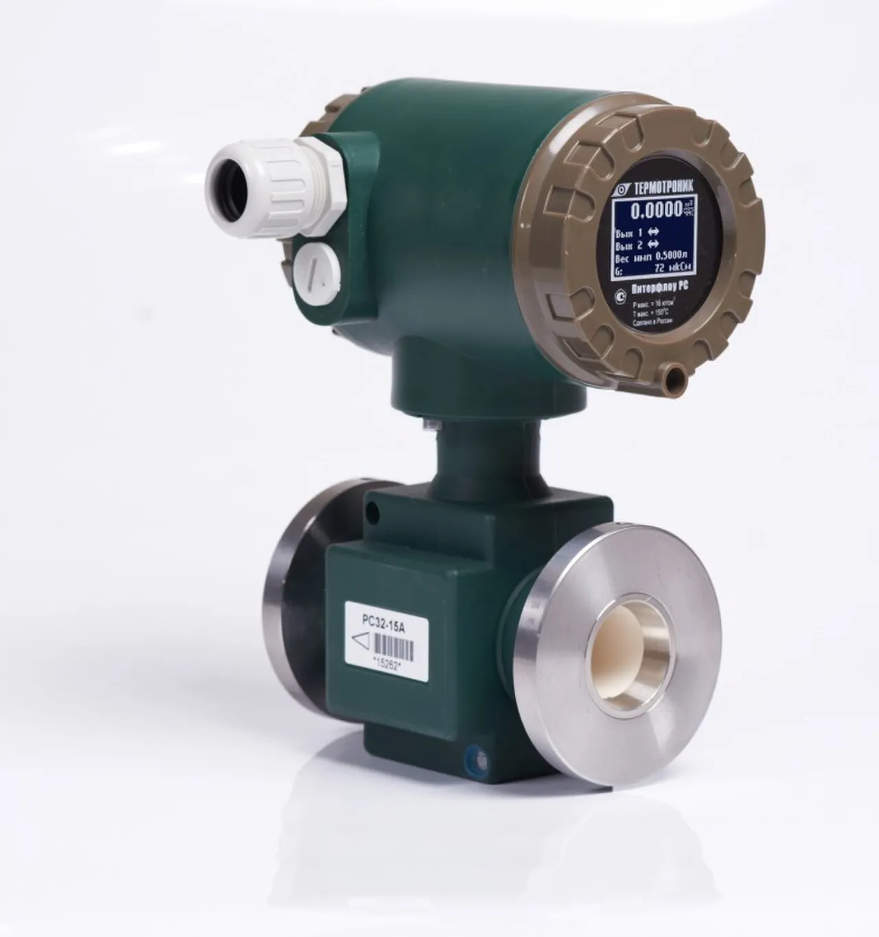
A batch controller is a dedicated instrument that totalizes volume from a flow meter and stops the delivery when a preset quantity has been reached. It conditions the pulse or analog signal from the meter, compares the running total against an operator-entered preset, and sequences the final control elements, typically a fast fill valve, a slow fill valve, and a pump contact, so that a tanker, an IBC, a day tank, or a mixing vessel receives a defined volume without an operator watching a scale. The instrument earns its keep in the final seconds of the batch: it slows the flow before the preset, learns the in-flight volume that keeps arriving after the close command, and pre-closes the next batch by that amount, converging on target within a few pulses. Well tuned systems land batches with a repeatability of 0.2 to 0.5 percent of quantity, and the honest statement is that the flow meter calibration, the valve behavior, and the piping dominate that number far more than the controller arithmetic.
Procurement engineers meet these instruments on chemical tanker and IBC loading racks, fuel and solvent dispensing stations, beverage syrup and dairy dosing rooms, water treatment polymer and chemical feed skids, and lubricant blending houses where additive shots must land inside a tolerance shift after shift. The decision this page settles is narrow: which meter pairs with the controller for the fluid, how many valve stages the job needs, what repeatability is achievable and what erodes it, how the instrument hands totals and recipes upward to a PLC or SCADA, and where the safety boundary sits, because a batch controller is a convenience and accuracy device, never the certified overfill protection layer. The answer lands as an RFQ line set: meter type and size, K factor and proving basis, valve count and staging fractions, fail state of every valve, the communication map, and the acceptance test that demonstrates the repeatability number before shipment rather than after the first disputed load.
This page treats the batch controller as a purchasing object: what the pulse totalization arithmetic actually does, how two stage valve sequencing and after run correction land a batch on target, which meter and final control element pair with which fluid, and how the whole set is written into a defensible RFQ. It is written for engineers who issue purchase specifications and acceptance tests, not for readers who want a brochure summary.
Chapter 1 / 06
What a Batch Controller Is and What Is Being Decided
Physically, a batch controller is a front-of-panel or field-mounted instrument with a numeric display, a keypad or configuration interface, one or two pulse or analog inputs from the flow meter, a handful of relay or transistor outputs wired to valves and pumps, and a serial port, most commonly Modbus RTU over RS-485. Logically, it is a totalizer with a state machine: idle, running, paused, batch complete, and alarm states, driven by start, stop, reset, and pause commands from pushbuttons or a supervisory system. Behind that modest description sits the entire economics of automated filling, because every loadout that does not need an operator with a dipstick and a clipboard pays for the instrument within months.
What is actually being decided in this purchase is three commitments at once. First, the measurement commitment: the controller is only as good as the flow meter feeding it, so the meter technology, size, and calibration are part of the same purchase decision even when they land on different purchase orders. Second, the actuation commitment: how many valve stages, what fail state, and whether the final element is a valve at all or a pump speed command. Third, the integration commitment: what the controller keeps for itself, the certified totalization and the front panel fallback, and what it hands to the control system, recipes, batch records, and alarms. A buyer who treats the controller as a 24 V DC gadget bought on price will rediscover all three commitments during commissioning at a much higher hourly rate.
The accuracy statement deserves respect because it is where specifications go wrong. The controller counts pulses with essentially zero arithmetic error and lands its relay commands deterministically; the repeatability of a landed batch, 0.2 to 0.5 percent on well tuned systems as a vendor-typical band, is consumed by the measurement and the hydraulics: meter calibration drift, air entrapment in the first seconds of filling, valve closure variation, line pack, and surge tank effects. Accuracy against a traceable standard belongs to the flow meter alone, and repeatability belongs to the whole skid. Writing a specification that demands 0.1 percent batch accuracy from the controller while buying an uncalibrated meter and a sticky valve is the classic self-inflicted wound of this product class.
The controller also sits inside a small society of companion instruments, and the RFQ should name them. Upstream, a flow switch serves as a dry-run or empty-line interlock so the controller never totalizes a meter spinning on air. A pressure transmitter on the skid header confirms that supply pressure was in band during the batch, which is the first diagnostic when overruns wander. Downstream, the valves or pump contact execute the sequence. Upward, a PLC or SCADA hosts recipes and records but, in the architecture this page recommends, does not own the certified total. Each of those devices has its own encyclopedia leaf, and this page links them where the batch controller depends on them rather than re-explaining them.
What is being decided, compressed to one sentence: whether preset quantity delivery at a stated repeatability, with a stated meter, stated valve staging, and a stated integration boundary, is bought as a working loop with an acceptance test, or assembled from parts and argued about later. The chapters that follow supply the arithmetic, hardware families, datasheet rows, and selection logic needed to write it the first way.
Chapter 2 / 06
How the Control Loop Lands a Preset Batch
The arithmetic starts with the K factor, the number of pulses the meter produces per unit of volume. A small oval gear flow meter can deliver tens of thousands of pulses per gallon, vendor typical for the smallest sizes, which is why positive displacement meters dominate micro-dosing. A DN 50 electromagnetic flowmeter usually has its pulse value configured in volume terms, one pulse per 0.1 to 10 liters depending on line size and the maximum flow rate, because its raw measurement is an analog voltage, not a pulse train. A turbine flowmeter is specified the classical way, with a K factor in pulses per liter or per gallon that varies a few tenths of a percent across its linear range, for example 1,200 pulses per gallon at the calibration point for a 1 inch meter, vendor typical. The controller divides incoming pulses by the K factor, or multiplies by the pulse value, and the batch total is simply the counted pulses times the volume per pulse.
Pulse resolution sets the theoretical floor of the landing accuracy. Work a DN 25 water line at 3 meters per second: the cross section carries about 0.15 liters per second at 20 percent of full rate during slow fill, and a meter configured at 10 milliliters per pulse then delivers 15 pulses per second, so one pulse is 10 milliliters and the count itself is never the bottleneck. At that slow rate, a valve that closes in 300 milliseconds lets roughly 45 milliliters arrive after the command, four to five pulses, and that in-flight volume, not the arithmetic, is what the controller must manage.
Two stage sequencing is the standard landing maneuver. Fast fill runs with the main valve fully open, at whatever the pump and pipe deliver, until the total reaches a start fraction of the preset, set between 50 and 95 percent with 90 percent the common default. The controller then closes the fast valve and lets a smaller solenoid valve, or a throttled larger valve, carry the remaining fraction at 10 to 25 percent of full rate. The physics is simple: in-flight volume scales with velocity and closure time, so cutting velocity by a factor of five before the close command cuts the overrun by the same factor and makes it far less sensitive to supply pressure wobble. On the DN 25 example above, the same 300 millisecond valve that overruns 45 milliliters at slow rate would have overrun over 200 milliliters from full flow, plus line decompression.
After run correction, sometimes written as in-flight or overrun correction, closes the residual gap. When the controller issues the close command it keeps totalizing until the meter physically stops, records the overrun, and shifts the next pre-act point earlier by that learned amount. Convergence is normally within two to three batches, and the landed error settles to a few pulses. The honest caveat: the learned value is only valid while the physics that produced it holds. Change the product viscosity, the supply pressure, the tank back pressure, or the valve wear condition, and the learned overrun is stale, which is why the better instruments display and log overrun per batch so that drift is visible on the panel instead of hiding inside an average.
The final control elements have their own physics and the controller must be specified against them. A direct acting solenoid valve closes in 50 to 500 milliseconds depending on size and pressure class, vendor typical; a pneumatic diaphragm actuator with a throttling solenoid or positioner gives a controlled deceleration but adds air supply dependence; a pump stop command removes flow almost instantly but leaves line pack to drain through the check valve arrangement. Stiction is the enemy: a valve that hesitates 100 milliseconds extra injects a variable overdose that the learning cannot fully cancel because it is not repeatable. This is the engineering basis for the repeated field advice that the money spent on a quality valve pays back directly in batch tolerance.
The error budget summary, in the order the money goes: first the meter and its installation, straight runs, grounding, and freedom from entrained air at the start; second the valve quality and staging; third the learning discipline; and only then the controller, whose contribution is the deterministic part. Surge tanks upstream that trap compressed air, drop lines that partially drain between batches, and manifold configurations where another customer opens a valve mid-batch all show up as overrun scatter that no setting removes. A specification that acknowledges these mechanisms is one that suppliers answer with sharper quotations.
Chapter 3 / 06
Types, Construction, and Duty Boundaries
Mounting families first. Panel instruments, cut into a loadout console or control room desk, run from mains or 24 V DC and suit attended racks where the operator starts batches at the panel. Field instruments in IP66 or IP67 glass reinforced housings mount at the skid, take a wider ambient span, and often carry an integral display readable in daylight. The third family is batching hosted inside the meter transmitter itself: several electromagnetic flowmeter transmitters, the Siemens MAG 6000 line being a widely quoted example, carry preset quantity logic and valve outputs natively, which removes a box and a handshake and is an honest alternative whenever the application is one meter, one or two valves, and no complex recipe.
Output stage families decide what the controller can switch. Electromechanical relay outputs, typically rated 250 V AC at 2 to 3 A, switch solenoid coils and starter coils directly, are inspectable, and wear at the contacts. Transistor outputs, 30 V DC at 100 milliamps class, suit low power DC solenoids and logic inputs and never wear out mechanically. Triac outputs cover AC valve coils without contacts. Two stage control needs two outputs per valve pair or a double solenoid arrangement, and the wiring pattern, one output for fast fill, one for slow fill, must be drawn in the RFQ because the terms single stage and dual stage are used differently across catalogs.
Final control element families set the character of the skid. The valve-based pattern uses a full bore solenoid valve for fast fill and a smaller one, often one or two sizes down, for slow fill; plant air users replace the small solenoid with a throttled pneumatic diaphragm actuator on a ball or pinch valve for abrasive and viscous products. The pump-based pattern uses a metering pump for micro dosing, where the controller starts and stops the stroke and the volume per stroke is the resolution, or a gear pump on a VFD for gravimetric style feeding where speed trimming replaces valve staging and the controller output becomes a run command plus, on the smarter units, an analog speed reference. Each pattern has a chapter in the selection logic later; the construction point here is that the controller specification must state which pattern it must drive, because output counts, ratings, and analog options follow from it.
The meter is the sensor of the loop and the controller is specified around its signal, so the pairing table below is the center of this chapter. The rows state the fluid class each meter family owns, the signal it brings, and the caution that most often appears in commissioning reports.
Meter family
Fluid class it owns
Signal and pulse class
Commissioning caution
Electromagnetic flowmeter
Conductive liquids, acids, caustic, slurries, water based products above about 5 microsiemens per centimeter
Pulse output configurable, one pulse per 0.1 to 10 L class; also 4 to 20 mA rate
Empty pipe at start reads zero but entrained air columns bias totals; ground per manual
Clean, non fiscal water class duty, cooling and rinse loops
Moderate pulse rate, economical
Not acceptable where the total is billed or audited
Turbine flowmeter
Clean low viscosity hydrocarbons, solvents, fuels
Classical K factor, for example 1,200 pulses per gallon at cal point for 1 inch, vendor typical
Viscosity and wear shift K; prove on the actual product
Construction boundaries are equally concrete. Hygienic versions with polished wetted parts and clean-in-place tolerant housings serve syrup, dairy, and pharmaceutical dosing rooms. Hazardous area versions, with intrinsically safe pulse inputs fed through barriers or flameproof housings, serve solvent and fuel racks; the certificate, ATEX or IECEx, and the installation concept must be stated together because the barrier layout belongs to the skid design. Ambient span, vibration resistance at pump-adjacent mountings, and display readability in sunlight separate the industrial instruments from the lab-grade counters that look identical in a catalog thumbnail.
One boundary deserves its own sentence so it never travels silently: this instrument class totals liquid volume through a flow meter. Dry bulk and multi ingredient weighing systems, the concrete batching plant being the loudest example, weigh aggregates and cement on load cells with a different controller class, different accuracy economics, and different standards; the shared word batching does not make the equipment interchangeable, and the selection chapter returns to that line once, where it belongs.
Chapter 4 / 06
Key Specification Parameters
The datasheet rows below decide whether a quoted instrument can actually run the skid. Values are stated as the common industrial span, with the note that every row must be confirmed against the specific model datasheet before order.
2 to 8 outputs, assignable as fast fill, slow fill, pump, alarm
One stage, two stage, and skid interlock wiring
Displays and registers
Batch counter, grand total 10 to 12 digits, rate, overrun log
Operator control and audit trail at the panel
Communication
Modbus RTU over RS-485 standard; TCP and profiler protocols optional
Recipe hosting and record retrieval architecture
Memory retention
Totals and settings in non volatile memory, 10 year class retention
Behavior across power loss mid batch
Enclosure and ambient
IP66 or IP67 field housings; panel types 0 to 50 deg C ambient
Mounting environment and display readability
The K factor row deserves its own paragraph because it is where the quotation meets the calibration certificate. The controller accepts a K factor or a pulse value to six or seven significant digits; entering it is trivial, proving it is the work. Proving means delivering a known volume through the meter and controller together, from a calibrated scale tank, a volumetric prover, or a master meter, and comparing. The proving basis belongs in the RFQ: state the acceptance method, for example three consecutive proving runs within 0.2 percent of a gravimetric reference, and require the as-found and as-left K values in the handover documents. Without that line the repeatability claim in the brochure is a number without a witness.
Two stage parameters are configurable and the defaults are not neutral. The table below states the practical spans and the sizing logic that connects them.
Two stage parameter
Practical span
Sizing logic
Start fraction, fast to slow switch
50 to 95 percent of preset, 90 percent common default
Lower it for long lines and slow valves to shrink in-flight volume
Slow fill rate
10 to 25 percent of full line rate via small valve or throttled actuator
Set against velocity so closure time times velocity meets the overrun target
Minimum slow fill duration
5 to 20 seconds, enforceable in configuration
Guarantees the line reaches steady slow flow before the close command
Valve closure class
50 to 500 ms direct acting solenoid, vendor typical by size
Overrun scales with closure time; measure it, do not assume it
Learned overrun display
Per batch, with trend log on quality units
Makes drift from viscosity, wear, and pressure visible at the panel
Finally, the datasheet must state the behavior that shows up only on a bad day: what happens to a running batch on power loss, which outputs de-energize, what the totals retain, and how the instrument reports the interrupted batch on restoration. Quotations that are silent on power failure behavior are silent on the one scenario every loadout rack eventually meets, and the answer belongs in the specification, not in a phone call during a night shift.
Chapter 5 / 06
Selection Decision Factors and RFQ Language
The selection sequence runs as a checklist, and each line eliminates a class of quotations before price comparison begins.
State the batch: product, preset quantity range, tolerance as a percent of batch, and daily batch count, because duty cycle sizes the valve actuation class.
Choose the meter against the fluid, using the pairing table in chapter 3; if the product is billed or audited, exclude the economy meter families at this step.
Fix the signal: pulse with a stated K factor and proving basis for any tolerance tighter than 1 percent; analog integration only where the meter offers nothing else.
Choose the staging: one stage for tolerant fills at low velocity, two stage whenever tolerance is tighter than 1 percent or line velocity exceeds about 1.5 meters per second.
Choose the final element: valve pair, throttled pneumatic diaphragm actuator, metering pump for micro doses, or gear pump on a VFD where speed trimming fits the process.
Set the fail state of every output against the loss of power and air, and write it into the valve specification, not just the controller configuration.
Define the integration boundary: what the PLC hosts, what the controller keeps, and the protocol between them, Modbus RTU being the common floor.
Fix the acceptance test: proving method, number of runs, tolerance, and the records delivered at handover.
Meter selection against the fluid is the heart of it, so it is worth restating in prose. Water based chemicals, acids, and slurries with conductivity above roughly 5 microsiemens per centimeter belong to an electromagnetic flowmeter, which adds no pressure drop of consequence and tolerates solids. Loaded solvents, liquefied gases, and any delivery billed by mass belong to a coriolis flowmeter, at the highest cost per line and the least sensitivity to profile and entrained gas. Additives, oils, and viscous products dosed at low flow belong to an oval gear flow meter, whose enormous pulse counts make resolution trivial. Rinse water and cooling loops that are never billed can use a paddle wheel flow meter honestly, and clean low viscosity fuels and solvents at higher flows are classical turbine flowmeter territory. The controller does not care which family feeds it, but the tolerance budget, the strainer requirement, the grounding practice, and the proving method all do.
Against its neighbors, the batch controller holds defined ground, and the comparisons belong here rather than in a page title. A flow computer is the fiscal accounting instrument of custody transfer, running certified AGA and API calculation packs with sealed audit trails for money transactions; a batch controller is the quantity delivery instrument of a filling operation, and the two meet on loading racks where a preset fill must also produce a fiscal record, which is why several vendors sell both. A PLC can absolutely run batch logic with counter cards and code, and on complex skids it does; the dedicated instrument answers with hard totalization independent of the control program, a panel that works when the SCADA node is down, and configuration that an electrician can audit in ten minutes, so the practical architecture lets the PLC host recipes and records while the controller owns the count. And once, plainly, as a boundary: a concrete batching plant is a dry multi ingredient weighing system on load cells, a different equipment class in its entirety, and nothing on this page transfers to it despite the shared word batching.
The safety boundary must be written without wiggle. Overfill prevention for the receiving vessel is a separate, certified layer: independent level measurement with a shutoff path, overfill prevention valves where the practice requires them, and the alarm and procedure framework that API 2350 organizes for storage terminals and NFPA 30 frames for flammable liquids handling. Where a loop carries a safety integrity requirement, the function is designed per IEC 61511 with its own devices and proof tests. The batch controller improves the economics and accuracy of normal filling and nothing more; a specification that assigns it any safety instrumented function is wrong, and the correction is cheaper at RFQ stage than after an audit.
The application map below compresses the selection guidance for the project file.
Application
Typical construction to specify
Check before order
Chemical tanker and IBC loading rack
Electromagnetic flowmeter or coriolis flowmeter, two stage valve pair, field controller, Modbus to SCADA
Conductivity of every product; overfill prevention layer stated separately
Fuel and solvent dispensing
Turbine flowmeter or coriolis flowmeter, explosion proof solenoid valves, Ex rated controller or barriers
Legal metrology class where the delivery is sold, OIML or MID context
Beverage syrup and dairy dosing
Oval gear flow meter or mag meter in hygienic execution, CIP tolerant valves, polished controller housing
Clean in place effect on K factor and valve closure; EHEDG intent
Water treatment polymer dosing
Metering pump driven by controller, or gear pump on a VFD for gravimetric feed
Shot size against strokes per liter; suction head and day tank level
Lubricant blending additive injection
Oval gear flow meter, staged valves, recipe recall from PLC with totals kept local
Viscosity span across products against K factor and valve timing
The RFQ block should be written once and reused: quantity of controller positions and their mounting; meter family, size, lining and electrode materials, and the K factor or pulse value with its proving basis; signal type and threshold; number and rating of outputs with the assignment of fast fill, slow fill, pump, and alarm; the staging fractions and minimum slow fill time; the fail state of each output; the enclosure, ambient, and any hazardous area certificate with its installation concept; the communication protocol and the register map expectation; the memory retention behavior on power loss; the acceptance test method and tolerance; and the handover documents, as-found and as-left K values, overrun logs from the works test, and certificates. A quotation returned without the works overrun data or the power failure behavior answered is incomplete at any price.
Chapter 6 / 06
Installation, Standards, Failure Modes, and Maintenance
Wiring practice carries more of the reliability than any controller setting. Pulse lines run in shielded cable, grounded at one end, separated from power circuits, and kept short between the meter transmitter and the controller; long runs on skids get surge protection because inductive kicks from valve coils and starters travel the same trays. An electromagnetic flowmeter in the loop brings its own leaf-critical requirements, full bonding and grounding rings or liners per its manual, straight runs, and avoidance of valves immediately upstream that could jet the profile. Interlock wiring follows the philosophy fixed in chapter 5: a flow switch upstream proves liquid presence before a batch may start, and a pressure transmitter reading retained per batch gives the diagnostic trail for every erratic overrun investigation.
Valve fail state is chosen deliberately against the loss of power and air. Normally closed valves stop the product, which is the correct default where overfill is the dominant hazard; normally open valves let solidifying or struvite-forming products drain or keep circulation, which protects the pipe at the cost of delivery, and that trade must be signed off by process safety rather than defaulted by the electrician. Solenoid coils are sized against the controller contact rating with margin, and flyback elements are fitted across DC coils so transistor outputs survive. Where the final element is a pump, the starter interlock chain and the controller output are drawn so that a stuck contact cannot defeat the stop command.
Commissioning is where the repeatability number is either earned or forged. Prove the loop against a gravimetric scale or a master meter on the actual product, enter or confirm the K factor, then run at least three consecutive batches and read the landed errors and the learned overruns; convergence within two to three batches with a stable overrun value is the healthy signature. File the proving report with the as-left settings, and schedule the first recheck after a few hundred batches, because wear announces itself in the overrun trend long before a failed total.
The standards frame for this instrument class is assembled from several directions because no single standard defines a batch controller. Electrical safety follows IEC 61010-1 and EMC follows IEC 61326 for industrial process instruments; hazardous area versions carry ATEX or IECEx certificates with the installation concept stated alongside. Where the delivered quantity is a legal trade transaction, the meter and controller operate as a measuring assembly in the legal metrology frame, OIML R117 and the MID in Europe being the references the certifying body will name, and the accuracy class is claimed for the assembly, not the parts. Overfill prevention practice draws on API 2350 for terminal storage and NFPA 30 for flammable liquids handling, and any safety instrumented function follows IEC 61511 with dedicated devices. Citing these in the RFQ signals that the skid will be audited, and audited skids get better built.
Failure modes arrive in a familiar order. Relay contacts weld closed, the valve stays open, and the batch overfills until the independent layer acts; the mitigations are contact inspection, overtravel alarms, and the certified overfill layer specified separately. Valve stiction makes overruns scatter, and the trend display of learned overrun is the early warning. Air entrapment at batch start biases the meter, mag meters read low through an air column and turbine and gear meters overspeed, so bottom-fed drops, flooded suction, and a pre-fill purge belong in the piping design. Pulse loss from a broken conductor or a dead transmitter shows up as a batch that never completes, and the dual channel inputs offered on the stronger units catch lost and extra pulses electrically. Power loss mid batch de-energizes outputs to their fail states while totals survive in non volatile memory; the event log tells the operator what happened, provided the specification demanded an event log. K factor drift, most visibly on turbine meters when product viscosity changes seasonally, is caught by the proving schedule.
Maintenance is short, scheduled, and cheap against the alternative. Prove the loop quarterly on tight-tolerance racks and annually on utility dosing, and after any meter, valve, or product change without exception. Exercise and inspect valves and contacts on the same cadence, review the overrun trend monthly, and treat a step change in the learned value as a work order, not a relearn. Keep the strainer clean where the meter demands one and retain the handover documents, because the as-left K value is the baseline that makes future drift a measurement instead of an opinion.
FAQ
When should I specify two stage valve control instead of one stage?
Two stage control runs a fast fill valve until a start fraction, typically 90 percent of preset, then finishes through a small slow fill valve at 10 to 25 percent of full rate. One stage closes a single valve from full flow, so the in-flight volume is large and varies with supply pressure. Specify two stage whenever the tolerance is tighter than about 1 percent of batch, the line velocity exceeds roughly 1.5 meters per second, or the product foams on fast delivery.
How does after run correction learn the overrun?
After issuing the close command, the controller keeps totalizing until the flow meter physically stops, records the volume that arrived late, and shifts the next pre-act point earlier by that amount. Convergence normally takes two to three batches, after which the landed error is a few pulses. The learned value stays valid only while pressure, viscosity, and valve condition stay similar, so the overrun display and log on the panel are the honest way to watch it.
Which flow meter should pair with the controller for my fluid?
Conductive water based products belong to an electromagnetic flowmeter; billed or air-slug-prone deliveries to a coriolis flowmeter; low flow viscous additives to an oval gear flow meter; clean low viscosity fuels to a turbine flowmeter; and non billed rinse water to a paddle wheel flow meter. The controller accepts pulses from any of them, but tolerance, strainer, grounding, and proving requirements follow the meter family chosen, so decide the meter first.
What batch repeatability is realistically achievable?
Well tuned systems land batches with a repeatability of 0.2 to 0.5 percent of quantity, vendor typical, and the controller arithmetic contributes almost nothing to that budget. The meter calibration, valve closure consistency, entrained air at start, and line pack dominate. Demanding tighter numbers in a specification without a proving regime and quality valves does not improve the skid, it only moves the argument to commissioning.
How should the valves be wired to fail safely?
Choose the fail state against loss of power and air per hazard: normally closed valves stop the product and are the default where overfill leads the risk list, while normally open valves protect solidifying products by allowing drain or circulation at the cost of delivery control. Write the fail state into the valve specification, size solenoid coils against the controller contact rating with margin, and fit flyback protection on DC coils so transistor outputs survive.
How does the controller integrate with a PLC or SCADA?
The common pattern is Modbus RTU over RS-485: the supervisory system writes presets and start commands, and reads batch counters, grand totals, rates, and alarm states. The recommended boundary keeps the certified totalization and the panel fallback in the dedicated instrument while the PLC hosts recipes and records. Where the delivery is also a fiscal transaction, a flow computer takes the accounting role alongside, and the two coexist on loading racks routinely.
How do I set and prove the K factor?
Enter the meter K factor or pulse value from its calibration certificate to the full digits the controller accepts, then prove the loop rather than trusting paperwork: run a known volume through the meter and controller together against a gravimetric scale, volumetric prover, or master meter, and require consecutive runs inside the stated tolerance, for example 0.2 percent. Record as-found and as-left values at handover, and re-prove on a schedule and after any product, meter, or valve change.