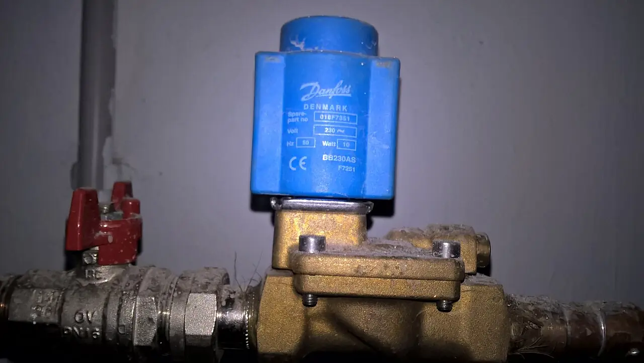
A four way valve is a directional control valve with four functional flow paths: one pressure port P, one exhaust or tank port T, and two working ports A and B. Shift it and it reverses the circuit, feeding supply to one side of a double acting cylinder while venting the other, which is the elementary act of machine automation. Engineers write the name in port notation more often than in words: a 4 way valve with two positions is a 4/2, the five port version with separate exhausts is a 5/2, and the three position 5/3 adds a center condition that holds, floats, or vents the actuator. The same architecture in hydraulic form is the 4/3 spool valve on CETOP and ISO 4401 subplates, switching oil at up to the 315 bar class.
Procurement engineers buy these valves by the thousand for clamp fixtures, gates, pushers, and quarter-turn process valve actuation, and the decision this page settles is precise: which porting configuration, which actuation and return scheme, which mounting standard and size, and which electrical envelope the RFQ must name so the cylinder behaves the same way on the third shift as on the first. The answer is a line set: configuration, size and flow, pressure class, coil voltage and connector, return type, and the air preparation hardware upstream. Every chapter feeds that line set, and the failure catalog at the end explains what happens when one row is left blank.
This page treats the four way valve as a purchasing object: how the porting grammar of 4/2, 5/2, and 5/3 maps onto circuit behavior, how pilot operation and return schemes set the failure story, what ISO 5599 and CETOP mounting sizes deliver in flow, and how coils, connectors, and air preparation combine into a defensible RFQ. It is written for engineers who issue purchase specifications, not for readers who want a brochure summary.
Chapter 1 / 06
What a Four Way Valve Is and What Is Being Decided
Port notation is the grammar of the purchase, and it is worth two minutes at the start. Ways are functional flow paths, positions are stable spool states. A 4/2 has four ports, P, A, B, and one shared exhaust, and two positions: P feeds A while B vents, or P feeds B while A vents. The 5/2 splits the exhaust into two ports, one per working side, which is the whole reason it exists. The 5/3 adds a center station with a chosen condition. Hydraulic 4/3 valves add the tank port T and live on standardized subplates. Writing 4 way valve, five port, or four way two position in an RFQ describes hardware in this family, and the port count is the unambiguous part of any such description.
What is being decided is behavior, not just hardware. The configuration decides whether each cylinder side can be speed controlled independently. The return scheme decides what happens on power loss: a spring return valve fails to a defined end, a dual solenoid valve latches wherever it sits. The center condition on three position valves decides whether a stopped load holds, floats, or vents. The size decides whether the valve is the bottleneck in the circuit. Those four rows, plus the coil voltage, are the whole purchase decision, and the rest of this page puts verified numbers under each one of them.
The family umbrella is the directional control valve, which spans two position on/off air valves, the three way valve that runs single acting cylinders and diverts single streams, proportional valves that throttle anywhere in the stroke, and banked valve islands. This page's subject sits at the center of that family: enough ports to reverse a double acting actuator, simple enough to switch in tens of milliseconds. The smallest members are sold simply as a solenoid valve in 2/2 and 3/2 configurations; the largest hydraulic members steer excavator and press circuits. The selection chapter draws the boundaries between all of them.
Every valve sits in a station, and the station is what the RFQ should describe. Upstream: an air preparation chain, typically an FRL unit delivering filtered and regulated air, with a dryer behind it in plants that hold an instrument air standard. The valve itself, or a valve island of several sections on a common manifold base. Downstream: meter out flow controls at the cylinder ports, exhaust silencers, and position sensors on the cylinder body feeding the controller. The electrical side lands on a PLC digital output card, with connectors standardized so any electrician can swap a coil at 2 am without a drawing search.
The consequences of a lazy row are concrete. A monostable valve specified without a thought for power loss parks the process wherever the spring says, not wherever the risk assessment says. An undersized valve turns a 2 second stroke into a 4 second stroke and production blames the cylinder. A closed center hydraulic valve without a relief path deadheads the pump. None of these are exotic, and all of them arrive at commissioning. The chapter order of this page is chosen so that each of those mistakes is caught on paper first.
Chapter 2 / 06
How the Porting Reverses Flow
Inside the valve, a cylindrical spool with machined lands slides in a bore with drilled ports. The lands block or connect the port galleries: in one position P communicates with A and B with the exhaust, in the other P with B and A with the exhaust. The spool shifts when a coil or a pilot signal pushes it and returns when the spring or the opposite coil pushes back. Poppet constructions replace the spool with seated discs for near zero leakage duty, at some cost in flow per size, but the spool remains the default because it is cheap, fast, and tolerant of marginal air.
Actuation divides into direct and pilot operated. A direct solenoid coil moves the spool against whatever the circuit pressure puts in its way, which bounds force at small sizes. Pilot operated valves use a small direct acting solenoid to route supply onto a piston that does the heavy shifting; the architecture needs a minimum pilot pressure of about 1.5 to 2 bar class, drawn internally from the supply or fed externally. External pilot is the required choice on vacuum and low pressure circuits, where the internal supply cannot be trusted to shift the spool at all. Manual overrides, a pin or lever that shifts the spool by hand, belong on every commissioning checklist and every fault-finding cart.
Return schemes set the failure story. Monostable: one coil and a spring, position lost on de-energization. Bistable: two coils and no spring, last position latched with a pulse, which saves coil heating and power but offers no defined fail position. Detent mechanisms hold position mechanically on some hydraulic valves. Response times for pneumatic solenoid valves run 10 to 60 ms class from coil to full shift, with small direct acting valves at the quick end and size 03 pilot valves at the far end; hydraulic valves add line oil volume, so their installed cycle looks slower even when the spool itself is fast.
Flow sizing is arithmetic, not folklore. Take a 63 mm bore cylinder on a 300 mm stroke: swept volume is about 0.94 L per extension, so a 2 second stroke consumes roughly 28 L/min of supply, and the retract side exhausts a similar volume minus the rod through the valve. A size 01 ISO 5599 subbase rated in the 500 to 1,200 L/min class carries that with an order of magnitude of margin; the real restriction ends up being the speed control needle and the fittings. The rule: size the valve so that it is not the restriction, then tune speed at the cylinder ports rather than by starving the valve or dropping the header pressure.
The electrical envelope is standardized and cheap to specify correctly. Coils come in 24 V DC at 1.5 to 6 W class and 230 V AC with inrush several times holding current, which is why an AC coil that never seats burns out and why the shading coil exists at all. Connectors follow EN 175301-803 form A, the round industry connector, with LED indication and suppression options built into the housing. Protection class IP65 with the connector seated and correctly oriented is the plant floor norm. On DC circuits the flyback path lives in the connector or the output card; a PLC transistor output driving an unprotected coil is a slow motion failure of that card.
Chapter 3 / 06
Types, Construction, and Duty Boundaries
The 4/2 is the compact ancestor: four ports, two positions, one exhaust shared by both working sides. It runs double acting cylinders where independent speed control per side is not needed, and it survives in legacy machines and price driven designs. Its structural weakness is the shared exhaust: a meter out throttle at the cylinder sees both sides' flow through one port, so extend and retract speeds are coupled, and a quick exhaust valve cannot be fitted per side. Modern practice moves to the 5/2 for almost no cost difference.
The 5/2 is the workhorse: five ports, two positions, separate exhaust per side. Independent meter out controls at each cylinder port, quick exhausts where the load helps, exhaust routed to a common silencer or separately as noise and hygiene require. Process plants know it in another costume: the air solenoid valve mounted on a quarter-turn actuator per the NAMUR interface is a 5/2 in actuator duty housing, cycling a rack and pinion actuator on a ball valve, a butterfly valve, or a plug valve in divert service a few times a day.
The 5/3 adds a center position with a choice of condition. Closed center blocks both working ports and traps the cylinder mid stroke: a soft hold, not a lock. Pressure center feeds both sides and resists drift with balanced force, at some air cost. Exhaust center vents both sides and lets gravity take the load, the choice on fixtures that must drop or release on an emergency stop. The center condition is chosen against the safety concept, which is why chapter 5 treats it as a selection decision rather than a catalog option to be defaulted.
Hydraulic 4/3 spool valves are the same idea at the 100 to 315 bar class on standardized subplates, CETOP R351 and ISO 4401 mounting faces in sizes NG03 through NG10 for industrial duty. Center conditions matter more here because a hydraulic pump cannot be deadheaded safely: open center routes pump flow to tank in center and lets the actuator float, tandem center unloads the pump while blocking A and B to hold the actuator, and closed center blocks everything and relies on the relief valve. Choosing the wrong center is the classic hydraulic commissioning error, and a cooked pump or a cavitating line is the receipt.
Construction options that change the RFQ: subbase mounted sections that gang into valve islands sharing one supply and one exhaust per group; in-line bodies for stand-alone duty; cartridge valves that drop into manifold blocks for compact presses; poppet spools for leak critical holding; and NBR or FKM seals set by temperature and oil chemistry. The air solenoid valve sections of an island share the filtered air delivered by the FRL unit, and hygiene or noise rules may force separate exhaust routing per section. The table below fixes the configurations in one view.
Electrical integration is a construction decision made at cabinet design time, not at the valve. A single valve carries its own EN 175301-803 connector and two wires; an island can be wired section by section, or it can take a multi-pin block that carries the whole island to one cable, or a fieldbus module that puts every section on the machine network with diagnostics per coil. The bus route costs more on the valve hardware and less on every hour of commissioning and fault finding afterward, and the choice must be written into the RFQ because the three architectures do not convert into each other on site. Sections with LED indication at the coil let a technician see the electrical command standing in front of the machine, which halves most fault isolation arguments.
Configuration
Ports and positions
Typical duty
Watch out
4/2 pneumatic
P, A, B, one shared exhaust; 2 positions
Simple double acting cylinders, legacy machines
Shared exhaust couples extend and retract speeds
5/2 pneumatic
P, A, B, two exhausts; 2 positions
Default for double acting cylinders with meter out control
Silencer clogging slows the controlled side
5/3 closed center
P, A, B, two exhausts; 3 positions, A and B blocked in center
Soft mid stroke hold on clamp fixtures
Not a lock; spool leakage class still applies
5/3 pressure center
P to A and B in center
Drift resistance with balanced force
Continuous air consumption while centered
5/3 exhaust center
A and B vented in center
Gravity release on stop, float duty
Load falls on center; drop zone must be reviewed
Hydraulic 4/3 tandem center
P to T, A and B blocked in center
Pump unload with actuator hold on presses and feeds
Verify relief setting and hose volumes
Hydraulic 4/3 open center
All ports open to tank in center
High flow machines with fixed displacement pumps
Actuator floats in center; not for load holding
Chapter 4 / 06
Key Specification Parameters
The datasheet rows that decide whether a quoted valve matches the duty are consolidated below, followed by the size table that most order codes hide inside a three digit number.
Attribute
Typical range or options
What it decides
Configuration
4/2, 5/2, 5/3 with center condition; hydraulic 4/3 with center
Circuit behavior and the failure story of the actuator
Mounting
ISO 5599-1 size 01, 02, 03 subbase; in-line; CETOP R351 and ISO 4401 NG03 to NG10
Interchangeability, island strategy, and spare logistics
Flow capacity
500 to 3,500 L/min class across ISO sizes at 6 bar; Cv equivalents published
Whether the valve is the restriction in the circuit
Operating pressure
Pneumatic 0 to 10 bar, 16 bar heavy class; hydraulic to 315 bar class
Supply envelope, spikes, and subplate rating
Actuation and return
Solenoid direct or pilot, pilot minimum 1.5 to 2 bar; spring or dual coil
Failure position and pilot supply architecture
Electrical
24 V DC at 1.5 to 6 W class; 230 V AC; EN 175301-803 form A; IP65
Output card loading and maintenance swap speed
Response time
10 to 60 ms class, pneumatic solenoid, size dependent
Cycle time budget and machine rate
Temperature
0 to 50 deg C standard class, minus 10 to 60 deg C with options
Ambient and media limits, seal compound choice
The ISO 5599-1 size number is where flow, port thread, and physical envelope hide together, so it deserves its own table. Values are catalog classes at 6 bar; the vendor flow table for the specific spool governs, and spool variants inside one size can halve or double the nominal figure.
ISO 5599-1 size
Port thread class
Catalog flow class at 6 bar
Typical duty
01
G1/4
500 to 1,200 L/min
Small cylinders, dense valve islands, pilot stages
02
G3/8
1,200 to 2,300 L/min
Mid bore cylinders, 80 to 125 mm, general machines
03
G1/2
2,000 to 3,500 L/min
Large cylinders and high rate packaging lines
Three rows of the specification deserve prose because order codes compress them into silence. Pilot supply: internal pilot shares the working header and is correct for normal duties; external pilot must be specified for vacuum, low pressure, and any circuit where the header sags below the 1.5 to 2 bar minimum while the valve must still shift. Manual override: demand the pin or lever and label it, because commissioning without it happens with screwdrivers on live coils. Leakage: datasheets state internal cross port leakage class, and a buyer who needs a cylinder to hold must treat that number as the drift budget, then add locking hardware on top of it.
Duty rating and voltage tolerance decide whether the coil survives the electrical reality of the site. Standard solenoid coils carry a continuous duty rating, written as 100 percent energization, and a voltage tolerance of roughly plus or minus 10 percent at reference temperature; a machine whose 24 V bus sags to 21 V under full load is quietly operating every coil at the edge of that envelope, and hot panels push it over. Specify the coil insulation class against the panel ambient rather than the nameplate room temperature, and prefer DC coils where the supply is marginal, because the DC coil tolerates undervoltage as heat instead of failing to seat.
Chapter 5 / 06
Selection Decision Factors and RFQ Language
The family boundaries are drawn by ports and proportion. A single acting cylinder or a one stream divert needs a three way valve, not a four: fewer ports, simpler coil logic, lower cost. Continuous mid stroke speed control needs a proportional valve driven by an analog or bus signal; the switched 5/2 moves end to end and its speed lives in the flow controls, not in the valve. Within the switched family the directional control valve umbrella spans everything from a 10 mm in-line air solenoid valve to a banked island of twenty sections; the four way configuration is simply the port count that reverses double acting actuators, and choosing it is usually settled by counting ports on the actuator.
Process valve duty is where this valve meets the piping world. An on/off ball valve in divert service is rotated by a rack and pinion actuator fed by a 5/2, and a butterfly valve or a plug valve in low pressure slurry duty wears the same actuation. Modulating duty instead uses a pneumatic diaphragm actuator stroked by a valve positioner fed from a 4 to 20 mA loop, with an I/P converter inside or beside it, and the valve positioner with its I/P converter calibrates as one loop on the bench. That is continuous control, a different purchase with different documentation. The honest boundary: switched 5/2 for open and shut quarter-turn duty, the positioner chain for throttling duty, and a three way valve where the stream splits rather than reverses.
Center condition and return scheme are chosen against the risk analysis, not the catalog order code. If a fixture must drop on emergency stop, exhaust center or a dedicated dump valve does that; if a clamp must hold, closed center soft-holds, but a piloted check or a blocked and locked supply holds for real, and ISO 13849 stop category arguments decide which. Monostable returns to a defined end on power loss and is the default for fail predictable machines; bistable latches and saves power but parks wherever it was. Write the failure position for every actuator into the RFQ, one line each, and make the supplier quote against it rather than against a part number.
A worked example fixes the numbers. A packaging machine indexes a pusher with a 63 mm cylinder at two strokes per product: the PLC sequences a 5/2 island section per cylinder, reads the reed sensors on the cylinder body, and sets the belt rate through a VFD while the pusher air is metered out at the ports. The air comes from a dryer and an FRL unit feeding a common manifold; each valve section draws 24 V DC at about 2 to 4 W; cycle rate and coil wattage size the power supply, and exhaust silencers set the noise floor. The island also hosts the instrument isolation hardware for the header pressure transmitter and an instrument manifold for the differential pressure transmitter across the coalescer, so filter condition is watched while the machine runs. The bill of materials stays a paragraph long because every interface is a standard.
The decision sequence runs as a checklist, and each line eliminates a class of trouble before purchase.
Count the actuator ports: double acting means 5/2 territory, single acting or single stream diverting means a three way valve.
Decide the speed control topology: separate exhausts with meter out per side, or the coupled economy of a 4/2.
Fix the failure position per actuator: spring return, dual coil latch, or center condition, and write each one down.
Size flow from cylinder volume and cycle time, then confirm the ISO 5599 or CETOP size against the table in chapter 4.
Confirm the pilot supply: internal from the header, or external for vacuum and low pressure circuits.
Specify coils and connectors: voltage, EN 175301-803 form A with LED and suppression, IP65 seating.
Include air preparation and exhaust hardware: FRL unit, silencers, and the dryer dew point behind them.
Demand the datasheet rows the order code hides: response time, leakage class, and pilot minimum pressure.
The application map below turns the chapter into a one page RFQ companion.
Application
Construction to specify
Check before order
Clamp fixture holding on stop
5/2 monostable, spring return to release, meter out controls
Failure position matches operator access rules
Gravity drop gate
5/3 exhaust center or dedicated dump valve, both reviewed
Load falls on center; guard the drop zone
Conveyor pusher, 63 mm cylinder, 2 second stroke
Size 01 island section, 500 L/min class flow
Speed set at the port needle, not by starving the valve
The RFQ block should be written once and reused: quantity; configuration with center condition; mounting size and standard, ISO 5599-1, CETOP, or in-line with port size; flow class or Cv; operating pressure range; actuation and return scheme; coil voltage and connector per EN 175301-803 with LED and suppression; manual override requirement; silencers and speed controls included or excluded; and the datasheet rows to be returned with the quotation. A quote that answers a porting question with a part number alone is incomplete at any price.
Chapter 6 / 06
Installation, Standards, Failure Modes, and Maintenance
Installation quality is mostly air quality and plumbing discipline. Blow every line before the first connection, because swarf kills spool valves faster than any other single error; then keep the air dry and clean through the FRL unit, and remember that modern valves are built to run non lubricated, with the lubricator in the chain only for legacy air motors sharing the panel, and that a pneumatic diaphragm actuator on a throttling loop elsewhere in the skid chokes on the same dirty air that sticks a spool. Mount silencers on exhaust ports and inspect them: a clogged silencer is the quiet cause of slow cylinders and phantom PLC faults. Set meter out controls at the cylinder ports rather than at the valve, so the trapped volume between valve and piston stays out of the control problem.
Wiring practice protects the card and the electrician. Use the EN 175301-803 form A connector with LED and flyback built in, seat it correctly for IP65, and label the manual override pins so commissioning does not happen with screwdrivers on live coils. Keep valve and sensor cables separated from power cables and from VFD motor leads, which radiate switching noise into unreferenced DC commons. Feed island sections from a fused 24 V DC bus sized for the sum of coil wattage, plus inrush where AC coils remain, and stock one spare coil of each voltage next to the panel rather than in a distant store.
The standards frame is short and useful. ISO 5599-1 fixes the pneumatic subbase mounting interface so a size 02 valve from any maker drops onto the same manifold. ISO 4401 and CETOP R351 do the same for hydraulic NG03 to NG10 subplates. EN 175301-803 fixes the electrical connector. Safety context comes from ISO 13849: stop performance and safe exhaust are functions of a validated combination, and a switched directional valve alone is not a safety device, a point that machine audits press home. For process actuators, the NAMUR interface per VDI/VDE 3845 standardizes how the 5/2 mounts directly on the actuator body, which removes a length of tubing and a leak point from every cycle.
Failure modes follow a familiar script. Solenoid burnout: a sticking spool or undervoltage holds the coil at inrush on AC, and the coil cooks; diagnose the spool, not just the coil. Spool sticking: varnish and lubricant washout from wet, oily, dirty air, cured by upstream filtration and dryer discipline rather than stronger springs. Weak return springs leave the valve shifted halfway, and the cylinder creeps or stalls. Cross port leakage through worn spool lands drifts the cylinder under load, the classic symptom of a valve past its service life. Pilot starvation on external pilot circuits that share an unfiltered header, silencer clogging that slows the metered side, connector ingress that defeats IP65, and on hydraulic valves cavitation and pump damage from the wrong center condition round out the list.
Commissioning closes the loop between the specification and the hardware. Stroke every actuator on air before the first product, measure the extend and retract times against the cycle calculation, and record them as the baseline for condition monitoring. Exercise every manual override once, then verify it was returned: an override pin left engaged is a classic intermittent fault that survives for months before anyone thinks to look. Prove the failure behavior by dropping coil power on purpose, one actuator at a time, and confirm each one lands where the RFQ said it would. On hydraulic systems, check the center condition against the pump load before the first press cycle. Two hours of this discipline buys back the blank rows of the specification and the entire chapter you would otherwise write about the startup argument.
Maintenance is calendar light and symptom driven. Swap spool and seal kits on a stroke count or years in service basis for hard working valves, replace coils with the power isolated and the connector standard on hand, and log response changes: a stroke that was 30 ms and is now 80 ms is reporting air quality before it reports failure. Panels that mix motion and measurement get a shutdown routine: air off and locked at the isolation valve, and the transmitter side isolated through its instrument manifold so measurement stays in service while the machine side is opened. Keep one full valve of the highest criticality configuration on the shelf; the cost of that shelf position is one unplanned stop, amortized on the first night shift it saves.
FAQ
When should I specify a 5/2 valve instead of a 4/2?
Specify the 5/2 whenever each cylinder side needs its own exhaust circuit. A 4/2 shares one exhaust between both sides, so a meter out speed control on one side also throttles the other. The 5/2 gives separate exhaust ports per working side, letting independent flow controls set extend and retract speeds, and it accepts quick exhaust valves per side. At equal size the 5/2 costs little more and is the industry default for double acting cylinders.
What is the difference between monostable and bistable operation?
A monostable valve has one solenoid and a spring return: it holds the energized position only while the coil is powered and springs back on loss of signal or supply. A bistable valve has two solenoids and no spring: a pulse moves it and it latches the last position, saving coil power, but it will not fail to a defined position on power loss. Choose monostable for fail predictable machines, bistable for energy and heating limits.
When is a pilot operated solenoid needed instead of direct acting?
Direct acting coils shift the spool against flow and pressure up to a modest limit; above that, pilot operated valves use supply air routed through a small direct solenoid to do the shifting. Pilot operation needs a minimum pilot pressure of about 1.5 to 2 bar, taken internally from the supply or fed externally. Specify an external pilot feed for vacuum, low pressure, or any circuit where internal pilot pressure cannot be guaranteed.
How do I size the valve for a cylinder?
Compute swept volume per side and divide by cycle time. A 63 mm bore cylinder with 300 mm stroke moves about 0.94 L per extension; a 2 second stroke needs about 28 L/min of supply plus margin, and the exhaust side dumps a similar volume. Match the flow rating at 6 bar, around 500 L/min for a size 01 subbase, so the valve is not the restriction, then set final speed with meter out controls at the cylinder ports.
Which center condition holds a load mid stroke?
A 5/3 closed center blocks both working ports and traps the cylinder, holding position against moderate load; pressure center feeds both sides and resists drift with balanced force; exhaust center vents both sides and lets the load float. In hydraulic 4/3 valves, tandem center unloads the pump while blocking A and B, and closed center holds load but deadheads the pump against relief. None of these is a safety lock: add redundant dump and block hardware for that duty.
How should coils be wired to a PLC output?
Use 24 V DC coils with the connector standardized as EN 175301-803 form A, with LED indication and built in suppression in the housing. Drive them from transistor output cards rated above coil holding current, and never rely on the card alone for inductive kick: flyback diodes in the connector or the card protect the output stage. Keep valve cable runs separated from power and motor cables, and check connector seating for IP65 integrity on washdown machines.
Why does my cylinder creep when the valve is centered?
Cross port leakage is the usual cause: spool wear or seal degradation lets air bleed from supply past the lands to the working port, and the cylinder drifts under load. A 5/3 closed center reduces but does not eliminate creep, because directional valves carry specified leakage allowances and are not locking devices. For a position that must hold, add piloted check valves at the cylinder ports or a mechanically locked blocking valve.