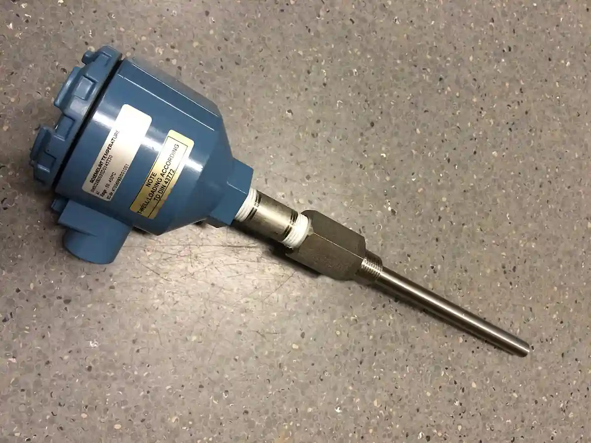
An immersion heater is a bank of metal-sheathed resistance elements placed directly into the liquid or gas being heated: water, oil, chemicals, heat transfer fluid, molten media, or process air. Each tubular element is a nickel-chromium coil packed in compacted magnesium oxide inside a sheath of copper, steel, stainless, or alloy, and essentially all of the electrical power drawn leaves through the sheath into the fluid. The controlling engineering number is watt density, watts per square centimeter of sheath: clean water tolerates 2.3 to 9 W/cm2, oils 1.2 to 3.1 by viscosity and circulation, air and gas 1.2 to 2.7 with velocity, and exceeding the medium's limit cooks the film on the sheath until the element fails. Plants call it an electric immersion heater, a tank heater, or a screw plug heater by its mounting, and the flanged, screw plug, and over the side families are treated in this page as types of one product.
Procurement engineers meet these heaters on water storage and calorifier duty, on heat transfer fluid systems, on caustic and chemical process tanks, on plating and anodizing baths, on fuel oil storage and LPG vaporizing, and on freeze protection of lines and fire loops. The decision this page settles is narrow and practical: the kilowatts implied by a heat-up calculation, the watt density the medium tolerates, the sheath and mounting hardware the chemistry allows, the enclosure and area classification the site demands, and the control and interlock chain that keeps the elements wet and bounded. The answer lands as an RFQ line set: kW, watt density, sheath, mount, control, protection, and code scope.
This page treats the immersion heater as a purchasing object: the resistance physics behind watt density, the heat-up arithmetic that fixes kilowatts, the sheath and mounting hardware that survive the chemistry, the control and interlock chain that keeps elements alive, and how all of it is written into an RFQ. It is written for engineers who issue purchase specifications, not for readers who want a brochure summary.
Chapter 1 / 06
What an Immersion Heater Is and What Is Being Decided
The product is energy conversion at a surface. An electric immersion heater puts the heat source inside the fluid: there is no combustion, no flue, no stack loss, and no steam plant between the power panel and the process, so essentially every kilowatt drawn is delivered into the liquid at the sheath wall. The trade is equally direct: electrical demand and demand charges replace fuel and steam infrastructure, and the hardware is judged by how long it holds its sheath temperature inside the fluid it was bought for. That is why the two numbers that decide the purchase are kilowatts, the duty, and watt density, the intensity, and why a quotation that states only the first one has answered half the question.
What is actually being decided is six commitments at once. First, the duty: kilowatts from a heat-up calculation on the real mass, real specific heat, and real time available. Second, the intensity: watt density the medium tolerates, which sets element count and heated length. Third, the materials: sheath alloy against the chemistry, mount hardware against pressure and code. Fourth, the style: flanged bundle, screw plug, or over the side, with circulation and process air duty as adjacent rows of the same table; chapter 3 covers all of them as types of this one product rather than as separate machines, so none of them earns a twin page. Fifth, the control chain: sensor, controller, power switching, high limit, and interlocks. Sixth, the environment: enclosure rating and area classification. Each commitment has a chapter below, and each becomes a line in the RFQ.
Against the thermal machinery beside it the heater is the point source, and one boundary deserves plain language: this page does not replace the heat exchanger leaves. A shell and tube heat exchanger moves heat from plant steam into process liquid with cheaper energy per kilowatt-hour and a condensate system attached; a plate heat exchanger does close-approach liquid duty in a compact frame; an air-cooled heat exchanger rejects heat to ambient air where water is scarce; a desuperheater conditions steam rather than heating liquid directly. Where steam exists at the right pressure, the exchanger route is usually the cheaper energy and the electric heater the lower infrastructure cost, and the honest quotation prices that delta rather than hiding it. On the cold side, a chiller is the same purchase logic running backwards. The full selection argument belongs to chapter 5; the point here is that the immersion heater competes on installation simplicity and control precision, not on energy price.
The heater never works alone, and the RFQ should name its station. Sensing: the process temperature reaches the controller through an RTD Pt100 or a thermocouple seated in a thermowell beside the bundle, and where the plant logs to the DCS a temperature transmitter carries the same measurement onward. Protection: a level transmitter or level switch interlocks power so elements never energize uncovered, and a safety relief valve handles the thermal expansion of blocked-in liquid. Fluid handling: circulation skids pair the heater with a pump and a pressure transmitter to confirm loop health, and the steam alternative that was not chosen would have carried a control valve and steam trap into the same budget line. A bimetal thermometer at the tank remains the local reading operators trust, and a solenoid valve on a quench or cooling line completes control of oversized batches. Naming the station lets one supplier check sensor seating, interlock logic, and power scope in a single pass instead of four arguments at delivery.
Three code frames organize the datasheet. Where the heater bolts into a pressure vessel, or its own shell is pressure-bearing as in a circulation heater, the ASME Boiler and Pressure Vessel Code Section VIII applies and the stamp is a purchase line. Mounting hardware follows dimensional standards: an ANSI B16.5 flange in class 150 or 300 for bundle mounts, NPT or BSPT threads for screw plugs. Electrical scope follows the site: NEMA enclosure ratings for general and moisture service, and for classified areas the NFPA 70 area classes with ATEX or IECEx certified Ex enclosures, which the established suppliers carry as catalog executions. A datasheet that states none of these three frames is a price tag with a kilowatt number on it, and it should be returned.
Chapter 2 / 06
How Resistance Elements Heat Fluid: Watt Density
Mechanically each element is a resistor in a pipe. A coil of 80 nickel 20 chromium alloy wire sits inside a metal sheath, surrounded by compacted magnesium oxide powder that conducts heat well and insulates electricity at operating temperature; current through the coil dissipates as heat, crosses the MgO pack, and leaves through the sheath wall into the fluid. Terminations exit at a cold pin or terminal post, and the assembly is sealed by welding or brazing at each end. The nichrome inside runs far hotter than the sheath; the margin between the coil's operating temperature and the sheath's rating is what element life is made of, and anything that raises sheath temperature, scale, coked oil film, sludge, or air, spends that margin.
Watt density is watts per square centimeter of sheath surface, and it is the number that decides element life. The arithmetic is honest and worth running once by hand: a 3 kW element of 8 mm sheath diameter carrying 1.3 m of heated length exposes about 330 cm2 of sheath, which lands near 9 W/cm2, the top of the clean water band; the same kilowatts spread over 2.6 m of heated length, a longer bundle or a folded leg, halve the intensity to about 4.5 W/cm2, which most oils tolerate under circulation. Buyers should demand the watt density per element rather than the bundle average a catalog quotes, because a bundle of high intensity elements in a short wet length fails exactly like a single element run too hot, only more expensively.
Sizing the duty is one formula and one honesty check. In words: kilowatts equal the mass heated multiplied by specific heat and by temperature rise, divided by the heat-up time, and the answer is grown by 10 to 25 percent for tank losses and margin. A worked example: raising 5,000 L of water, about 5,000 kg at 4.19 kJ per kilogram per degree, by 50 deg C in 3 hours asks about 97 kW before losses and about 110 kW with a modest margin, which is flanged bundle territory and never a screw plug. An oil example lands differently: 3,500 kg of thermal fluid at about 2.1 kJ per kilogram per degree raised 80 deg C in 4 hours asks roughly 41 kW before losses, but at oil limits the sizing problem becomes element count and heated length rather than kilowatts, because intensity, not power, is the binding constraint.
The film decides everything. Heat leaving the sheath crosses a boundary layer of stagnant fluid, and the temperature drop across that film rises with watt density and falls with convection: still oil runs a thick hot film, circulated water a thin one. In oil service the failure chemistry is coking: the film layer carbonizes on the sheath, the coke insulates, the sheath runs hotter under the same watt density, and the process accelerates until the element burns out or the oil cracks and fouls everything downstream. In water service the analogue is scale: mineral hardness deposits fastest exactly where the sheath is hottest, and a thin scale layer can hold the sheath hundreds of degrees above the bulk liquid. The remedies are identical in both chemistries: lower the watt density, lengthen the elements, or move the fluid.
The control chain exists to keep the sheath inside its design envelope. The basic execution is a mechanical thermostat with a sensing bulb seated in a thermowell in the tank, switching power through a contactor; the process execution is an electronic PID controller reading an RTD Pt100 or a thermocouple in a thermowell, driving contactors for staged elements, solid state relays for quiet switching, or SCR power controllers for tight bands and large loads. Two protections are mandatory practice everywhere credible: a high-limit cutout with manual reset, set below the maximum sheath temperature the medium allows, and a level or flow interlock, wired from a level transmitter or flow switch, that drops power before the heated length can uncover. Circulation skids add their own logic: the pump, commonly on a VFD for controlled flow, must prove flow before the contactor closes, because a heater running into still or absent fluid is a slow fuse.
Dry fire is the failure that pays for all the interlocks. An element rated near 3 W/cm2 in oil that uncovers and runs in air loses the cooling of the liquid film and climbs to sheath temperatures the MgO pack, the braze, and the terminations cannot hold; element burnout within minutes is the documented result, and a grounded element or a carbonized terminal block follows the same event. That is why the interlock chain, level transmitter, flow proof, and manual-reset high limit, is specified with the heater instead of being retrofitted after the first burnout, and why chapter 6 treats the insulation resistance test as a routine maintenance number rather than a post-mortem.
Chapter 3 / 06
Heater Types, Construction, and Duty Boundaries
The flanged immersion heater is the industrial backbone. A bundle of U-shaped elements is welded or brazed into a pipe flange, ANSI B16.5 class 150 or class 300 typical, in sizes from 2 in to 14 in and beyond, and the flange bolts to a matching vessel nozzle with a companion gasket and studs. Power classes run from tens of kilowatts into the megawatt range per vessel, with three-phase supply standard above roughly 30 kW. Designs split into fixed bundles and replaceable bundle executions, where the element pack can be withdrawn through the flange without cutting the vessel open; the replaceable bundle costs more at purchase and repays it the first time an element group needs service. Duty: pressure vessels, storage tanks, and process vessels where kilowatts are serious and access matters.
The screw plug heater is the small-plant standard. Elements are brazed into a threaded plug, NPT from 1 to 3 in typical with BSPT and small flanged variants, and the whole heater screws into a tank boss or coupling; power runs from about 1 to 60 kW. Water and oil tanks, washers, diesel and lube service, and small process tanks are its work, and the economics are standard hardware, unit replacement, and no flange gasket to manage. The trade is capacity and immersion flexibility: a screw plug heater is bought when the duty fits it, not stretched to cover a flanged duty it was never sized for.
The over the side heater hangs in through the top of the vessel. A bracket or hook carries the element bundle over the rim, the terminal housing stays outside the liquid, and no nozzle is needed at all; power classes are lower, and the virtues are portability and replacement without draining the tank. Oilfield tank heating, sludge and paraffin warmers, plating and anodizing baths, and rented or temporary heat are its natural work. The honest limits are watt density discipline in poorly circulated product and mechanical protection of the hanging bundle against damage from heaters, agitators, or craned loads.
The circulation heater is the closed-loop sibling and stays on this page as a type rather than a separate product. A pressure-rated body carries the element bundle and adds inlet and outlet nozzles so fluid flows through a shell across the elements; internal baffles direct the flow, and the body usually carries its own thermowell and flow switch, with a pressure transmitter on the loop where the skid warrants it. Duty: heat transfer oil and fuel heating, LPG and fuel vaporizers, gas heating, and superheating service where the fluid must arrive hot and pressurized at a use point. A circulation heater accepts that the pump is part of the heater: flow proves power, and the pair is bought together on one baseplate.
Duct and process air heaters are the gas-side row of the same table. Elements cross a duct or sit in a heater body in the airstream, and the medium's poor heat transfer keeps intensity low, 1.2 to 2.7 W/cm2 class, rising within that band only when air velocity is guaranteed by design. Ovens, dryers, and process air trains buy them with the same control chains as liquid duty, with one substitution: an air flow proof is the interlock, exactly as level is for liquid, because an element bank in stagnant air cooks exactly like one in stagnant oil.
Materials follow chemistry, and the list is short and unforgiving. Copper sheaths serve clean water and wash duty. Steel serves oils where corrosion is absent. Incoloy 800 is the generalist, good to the 870 deg C class and the default for hot oil and high temperature duty. Stainless 316 covers corrosive and clean service; titanium earns its cost in brine, chlorides, and plating chemistry, where stainless pits; and PTFE or quartz sheaths carry ultra-pure acids that attack every metal. Flange and plug hardware matches the vessel, carbon steel or 316L, with wetted parts certificates closing the paper trail. Galvanic mismatch between sheath and vessel is a real failure mode, and it is decided at purchase, never discovered in service at a convenient time.
The type table compresses the families into one view; power classes and mountings are the common ranges of the established families and must be confirmed against the model datasheet before order.
Type
Mount and power class
Service access
Duty it wins
Flanged immersion heater
ANSI B16.5 class 150 or 300, 2 to 14 in; tens of kW to megawatt class
Replaceable bundle executions; vessel entry for fixed
Pressure vessels, large tanks, serious kilowatts
Screw plug heater
1 to 3 in NPT typical; about 1 to 60 kW
Unscrew and swap as a unit
Water and oil tanks, washers, small process
Over the side heater
Bracket over rim; lower power classes
Lift out without draining
Plating baths, oilfield tanks, temporary heat
Circulation heater
Body with inlet and outlet; flow-through duty
Bundle through body flange
Thermal oil, fuel and LPG vaporizing, gas heating
Duct and process air heater
Duct or body mount; 1.2 to 2.7 W/cm2 with velocity
Element bank removal from duct
Ovens, dryers, process air trains
Chapter 4 / 06
Key Specification Parameters
The datasheet rows below decide whether a quoted heater matches the duty; values are stated as the common industrial ranges of the established families and must be confirmed against the model datasheet before order.
Attribute
Typical range or options
What it decides
Kilowatt rating
1 kW screw plug to megawatt class flanged bundles
Duty coverage from the heat-up calculation plus margin
Voltage and phase
208, 240, 480, 600 V class; three phase above about 30 kW
Panel scope, breaker sizing, and staged circuits
Watt density
2.3 to 9 W/cm2 water; 1.2 to 3.1 oil; 1.2 to 2.7 air
Element life in the named medium; stated per element
Sheath material
Copper, steel, 316, incoloy 800, titanium, PTFE or quartz
Corrosion life and maximum sheath temperature
Mount
ANSI B16.5 class 150 or 300 flange, 2 to 14 in; 1 to 3 in NPT; over the side bracket
Vessel compatibility and service access
Enclosure
NEMA 1, 4, 4X, 7; ATEX or IECEx Ex executions
Siting in wet, washed, or classified areas
Control chain
Mechanical thermostat with bulb; PID with RTD Pt100 in a thermowell; contactor, SSR, or SCR
Temperature band, staging, and switching life
High limit
Manual reset cutout below maximum sheath temperature
Survival of a sensor or controller failure
Interlocks
Level transmitter or level switch; flow proof on circulation duty
Dry fire protection, the dominant failure mode
Code scope
ASME Section VIII stamp where pressure-bearing
Vessel acceptance, hydrotest, and nameplate
The watt density row is the one most often blurred in catalogs, so the medium guidance below states it as the family band each fluid class tolerates; the quoted value inside the band belongs in the purchase order per element, with the sheath material named beside it.
Medium
Watt density guidance
Sheath logic
Clean, circulated water
2.3 to 9 W/cm2
Copper or incoloy 800; watch hardness
Hard or scaling water
Lower half of the water band
Cleaning access priced with the heater
Oils by viscosity
1.2 to 3.1 W/cm2
Incoloy 800; circulation extends the top of the band
Heat transfer fluids
To about 2.3 W/cm2
Velocity and bulk temperature govern together
Air and gases
1.2 to 2.7 W/cm2 with velocity
Airflow guaranteed by design, not by hope
Corrosive baths
Low intensity, per chemistry
Titanium or PTFE; certificates with the lot
The type comparison below states the trade each family makes, which is what a specification meeting actually argues over once kilowatts and sheath are fixed.
Type
Trade
Check before order
Flanged bundle
Highest power and pressure capability; heaviest hardware
Nozzle class and schedule; gasket and stud scope; bundle withdrawal clearance
Screw plug
Cheapest installed; limited power and immersion
Boss thread condition; kW against the heat-up arithmetic
Over the side
No nozzle and full portability; lowest intensity discipline
Flow proof wiring before contactor; pump and VFD scope
Duct air
Gas-side duty with airflow as the interlock
Airflow proving device in the interlock chain, not bypassed
A complete datasheet must also state, per element: the watt density and the maximum sheath temperature in the named medium, element count and kilowatts per element, heated and cold lengths, the wiring schematic with terminal torque values, insulation resistance acceptance in the megohm class at 500 VDC, enclosure and Ex certificate numbers where classified, material certificates for wetted parts, the gasket and stud scope for flanged units, and the ASME stamp with hydrotest documentation where the code applies. A datasheet quoting bundle average watt density, or maximum sheath temperature in air rather than in the process medium, is describing a different heater than the one that will be installed.
Chapter 5 / 06
Selection Decision Factors and RFQ Language
The decision sequence runs as a checklist, and each line eliminates a class of quotations before price comparison begins.
State the medium honestly: specific heat, viscosity at operating temperature, chemistry including chlorides and any cleaning chemistry, and solids or sludge the bundle will live in.
Fix the duty: mass or volume, start and end temperatures, heat-up time, then kilowatts with 10 to 25 percent margin for losses.
Choose watt density from the medium, then element count and heated length that deliver it.
Choose sheath and hardware by chemistry: copper, steel, 316, incoloy 800, titanium, or PTFE, with flange or plug to match the vessel.
Fix the style by access and power class: flanged, screw plug, over the side, circulation, or duct air.
Specify the control chain: thermostat or PID, sensor in a thermowell, contactor, SSR, or SCR switching, manual-reset high limit.
Fix the protections: level transmitter or flow interlock, safety relief valve on the heated volume, phase failure relay on three-phase loads.
Fix environment and code: NEMA or Ex enclosure, ASME scope, panel and breaker scope, and the wiring documents that come with them.
Against the neighboring thermal machinery the electric heater holds specific ground, and the comparison belongs here in the selection chapter. Where plant steam exists, a shell and tube heat exchanger delivers heat at fuel-fired cost per kilowatt-hour, and the honest electric quotation prices the delta: no steam trap, no condensate return, no control valve maintenance, and no freeze risk on the steam line, against demand charges and wiring capacity. A plate heat exchanger does close-approach duty in a fraction of the footprint when a hot stream exists to exchange against. An air-cooled heat exchanger is the other side of the ledger, rejecting heat where cooling water is scarce. A desuperheater conditions steam for process use rather than heating liquid directly, and a chiller is the same architecture inverted for cooling. Within the electric station the instrumentation is shared logic: the thermowell seats the RTD Pt100 that rules the loop, the temperature transmitter carries the reading to the DCS, a bimetal thermometer gives the local check, a level transmitter holds the wet-interlock, a pressure transmitter watches circulation loops, a VFD sets pump flow, and a solenoid valve meters quench water when a batch overshoots. The safety relief valve on the heated volume is not optional: liquid blocked between closed valves expands when heated, and the relief is the defense the code recognizes.
The application map below turns that logic into a table the project file carries.
Application
Construction to specify
Check before order
Water storage and calorifier duty
Flanged or screw plug, copper or incoloy 800, 2.3 to 9 W/cm2
Hardness and cleaning schedule; level interlock setpoint
Heat transfer oil systems
Circulation heater, incoloy 800, about 2.3 W/cm2 with velocity
Flow proof before power; pump and VFD scope
Caustic and chemical process tanks
Flanged or over the side, 316 or titanium by chemistry
Wetted certificates; galvanic pair against vessel
Plating and anodizing baths
Over the side, titanium or PTFE sheath
Pull-and-clean schedule; mechanical protection of bundle
Fuel oil storage and viscous product
Flanged or over the side, steel or incoloy, 1.2 to 2.3 W/cm2
Small flanged or screw plug units, thermostat range suited
Low ambient enclosure; trace alternative priced
Process air and oven duty
Duct heater, 1.2 to 2.7 W/cm2 with guaranteed velocity
Airflow proof wired into the interlock chain
The RFQ block should be written once and reused. A complete block reads: media with specific heat and viscosity; mass or volume with the heat-up time and the calculation shown; operating and maximum temperature; pressure and vessel code scope; the watt density chosen for the media; sheath and flange materials; ANSI flange size and class, or NPT size, per mount; enclosure rating and area classification with certificate; thermostat or process sensor type with its thermowell; high limit with manual reset and the interlock list, level transmitter or flow proof; panel and power switching scope, contactor, SSR, or SCR; and the ASME stamp if the installation is pressure-bearing. A quotation returned without per-element watt density or without a maximum sheath temperature in the process medium is incomplete at any price.
Chapter 6 / 06
Installation, Standards, Failure Modes, and Maintenance
Installation is a coverage and torque exercise. The heated length must sit fully wet at minimum operating level with margin, and the level transmitter or switch that interlocks power is mounted so its trip point sits above the top of the heated length, not beside it; the control sensor's thermowell is placed where it reads tank reality rather than the element glow, and a bimetal thermometer at the shell gives the local check. Flanged units bolt up to the torque table with the companion gasket centered, and the joint is re-torqued after the first heat cycles because gasket relaxation on first heating is a design fact, not an installation error. Wiring follows the load: conductors and breakers sized for the amperes, terminal lugs torqued to the datasheet value, and a thermography baseline captured at commissioning while every phase is pulling. The safety relief valve on the heated volume installs with no isolating valve between it and the liquid, and the relief path is piped where it can discharge safely.
Commissioning verifies the chain, not just the heating. Megger the elements before first energize: insulation resistance from element to sheath in the megohm class at 500 VDC is the acceptance band, and a low reading on a new unit is a warranty conversation, not a startup delay. Force the level transmitter low and confirm power drops; trip the high limit and confirm it latches until manually reset. Run the heat-up and log the time-temperature curve against the design calculation, because that curve is the acceptance test for the whole purchase. On circulation units, prove the flow interlock at minimum VFD speed and confirm the pump proves before the contactor closes; stroke the solenoid valve on the quench line and watch it actually close. Record element resistances per phase and file them: the balance between phases is the baseline every future measurement is argued against.
The standards frame is short and enforceable. ASME Boiler and Pressure Vessel Code Section VIII governs pressure-bearing heater bodies and flange assemblies, with the stamp, hydrotest, and nameplate as purchase deliverables. ANSI B16.5 fixes the flange dimensions of bundle mounts, and thread standards fix the plug hardware. Enclosures follow NEMA rating types, classified areas follow the NFPA 70 classes, and Ex executions carry their ATEX or IECEx certificates, which the supplier's specification sheets state as the family reference. A purchase file that cites these by name transfers the burden of proof to the supplier, which is where it belongs.
Failure modes follow a short and predictable list. Dry fire burnout: the level dropped, the interlock was absent or bypassed, and the elements cooked in minutes; the fix is the interlock chain specified in chapter 2 and never defeated. Sludge blanket: the bundle insulates exactly like scale, common in fuel oil and plating duty, and the answer is watt density and a pull-and-clean schedule. Coking in oil: excessive watt density or dead zones, remedied by lower intensity or circulation. Scale in water: monthly inspection and cam-out cleaning on hard water, before the layer grows its own thermal runaway. Terminal faults: loose lugs and carbonized terminations announce on the thermography program, not on the control chart. Gasket leak on flanged units: re-torque after first cycles and replace at major service. Galvanic and chemistry attack: the sheath matched to the vessel and bath at purchase, with titanium where chlorides rule. Power-side faults: a welded contactor or a failed SSR drops one phase of a three-phase bundle, and a phase failure relay catches it before the elements do.
Maintenance is deliberately boring and trend driven. Monthly: visual on terminations and enclosure, insulation resistance spot check, scale or sludge inspection on the media that build it. Quarterly: thermography on terminal enclosures under load, element resistance balance against the commissioning baseline, interlock and high limit function tests. Annually: gasket renewal on flanged units, deep inspection of the bundle where access exists, contactor and SSR exercise, and calibration of the control sensor chain from thermowell to controller. Spares worth holding: a gasket set, one element group or a spare bundle for critical services, a contactor or SSR, and a spare sensor with its thermowell. The trend lines the log accumulates, resistance, insulation resistance, terminal temperatures, are what turn the next RFQ from a repeat purchase into a specification, which is how a purchasing file gets smarter instead of just older.
FAQ
How do I size the kilowatts for a tank heat-up?
Run the heat-up equation: kilowatts equal the mass heated times specific heat times temperature rise, divided by heat-up time, then add 10 to 25 percent for losses and margin. A worked example: 5,000 L of water raised 50 deg C in 3 hours asks about 97 kW before losses, roughly 110 kW with margin, which is flanged bundle territory. State mass, specific heat, real end temperature, and time in the RFQ; a heater bought on pipe size instead of this arithmetic is wrong in the expensive direction.
What watt density should I specify for oil?
Oils tolerate 1.2 to 3.1 W/cm2 by viscosity and circulation: thin, circulated oils work toward the top of the band, heavy stagnant product sits at the bottom of it. Above the band the oil film on the sheath carbonizes, the coke layer insulates, and sheath temperature climbs at constant watt density until the element burns out. Buy intensity with margin: more heated length at lower watts each, or a circulation pump to thin the film, is cheaper than the first unplanned outage.
How do I choose between flanged, screw plug, and over the side?
Power class and access decide it. Screw plug heaters, 1 to 3 in NPT and roughly 1 to 60 kW, suit small tanks and standard bosses. Flanged immersion heaters, ANSI B16.5 class 150 or 300 from 2 to 14 in, carry tens of kilowatts into the megawatt class on pressure vessels, with replaceable bundle executions for service access. Over the side units hang through the rim with no nozzle, portable and lower power, natural for plating baths and oilfield tanks. Circulation and duct air duty are the closed-loop and gas rows of the same family.
Why do heating elements burn out, and how do I prevent it?
Most burnouts trace to the sheath leaving its envelope: dry fire when the level drops below the heated length, a sludge blanket insulating the elements, coked oil film from excessive watt density, or scale in hard water. The protections are standard practice: a level transmitter or level switch interlock that drops power before uncovering, a manual-reset high limit, and watt density chosen for the actual medium. Megger the elements periodically; falling insulation resistance announces the failure months early.
What control chain does process duty deserve?
The basic chain is a mechanical thermostat with its bulb in a thermowell, switching a contactor, and it holds water tanks fine. Process duty deserves electronic control: a PID controller reading an RTD Pt100 in a thermowell, driving contactors for staged elements, solid state relays, or SCR power controllers for tight bands and large loads. Keep two protections regardless of chain: a manual-reset high limit set below the maximum sheath temperature, and the level or flow interlock that keeps the bundle wet.
Which sheath material suits my medium?
Match the sheath to the chemistry. Copper for clean water, steel for oils, incoloy 800 as the high temperature generalist good to the 870 deg C class, 316 stainless for corrosive and clean service, titanium where chlorides and plating chemistry destroy stainless, and PTFE or quartz for ultra-pure acids that attack every metal. The mistake that kills elements fastest is the near-miss: 316 in brine pits, and titanium in strongly reducing chemistry fares no better. Wetted certificates close the argument before the first element does.
When does an immersion heater need an ASME stamp?
When the heater body or flange assembly is pressure-bearing, on pressurized vessels, circulation heaters, and vaporizers, ASME Boiler and Pressure Vessel Code Section VIII applies, with the stamp, hydrotest documentation, and nameplate to match. Tank heaters bolting into atmospheric vessels usually sit outside code scope, but the thermal hazard is real regardless: liquid blocked between closed valves expands when heated, so a safety relief valve on the heated volume is standard practice whether or not the stamp is required.