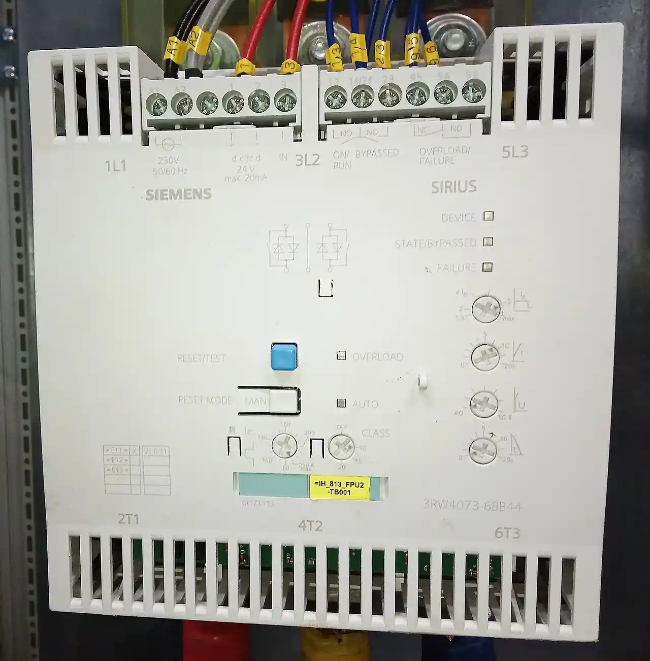
The soft starter versus variable frequency drive debate on pump duty bundles two questions: an electrical question about starting current, and a process question about flow control. This page separates them. A centrifugal pump started across the line draws 6 to 8 times full-load current, stresses couplings and bearings, and can slam the line with water hammer on stop. Both devices tame that start; only one changes how the pump runs afterward.
The decision rests on the duty profile, so this guide opens with a taxonomy of real pump duties, from tank transfer to fire pumps and deep-well submersibles, and marks which duty pushes toward which device. From there it works through starting physics and stop physics, affinity-law arithmetic with worked numbers, an extended specification parameter decoder, a six-step decision sequence with a total-cost table and an eight-point RFQ checklist, and field practice covering IEEE 519 harmonic studies, motor cable length effects, shaft grounding, PID sleep tuning, and dry-run protection.
This guide is aimed at industrial purchasing and design engineers. It covers 6 chapters from the selection problem, starting physics, and affinity-law energy math to a decision sequence, with 7 selection FAQs. Numbers reference IEEE 519 and IEC 61800.
Chapter 1 / 06
The Selection Problem
An across-the-line start on the AC motor driving a centrifugal pump pulls 6 to 8 times rated current until the rotor reaches speed. On a pump fed from a limited transformer, a standby generator, or a long cable, the same start means voltage dip, flicker, nuisance trips, and demand penalties; mechanically, the torque transient hammers couplings and the abrupt flow change can surge the line.
The two standard answers overlap only at the start. A soft starter is a starting device: it reduces voltage during acceleration and stop, then gets out of the way. A variable frequency drive is a running device: it controls speed continuously, and the gentle start comes almost free. The choice is a question about the duty: does the pump need different speeds, or only a polite start followed by full-speed running? The answer decides the hardware.
Six duty families, and where each one pushes. Pump duties are not interchangeable, and the duty profile decides the device long before price does. Transfer and fill-and-stop duty runs the pump at full speed into a tank or sump with a level switch; nothing varies except the start, so it is classic soft-starter work. Pressure boosting holds a header setpoint against a fluctuating demand curve, which is variable-speed work: a VFD running PID with a sleep function, usually on a multistage pump, with the soft starter plus pressure-reducing arrangement relegated to small systems. Chilled water and heating loops modulate on differential pressure or temperature and are equally VFD territory. Raw water intake combines seasonal flow variation with long lines, so the stop method and a surge study matter as much as the start. Fire pumps per NFPA 20 sit in a listing regime of their own: only listed fire pump controllers apply, the standard constrains what reduced-voltage or variable-speed starting is acceptable, and neither a standard soft starter nor a standard VFD is admissible on its own merits. Deep-well submersible duty presents high breakaway torque and very long motor cables: fixed-speed wells start on soft starters engineered for submersible duty, wells matched to variable aquifer yield use VFDs, and the cable and motor insulation checks in chapter 6 apply in full.
Duty family
Flow profile
Device it pushes toward
Deciding constraint
Transfer, fill-and-stop
Full speed, 2 to 10 starts per hour
Soft starter
Inrush and surge control only
Pressure boosting
Modulates against a header setpoint
VFD with PID and sleep
Cube-law savings plus no-cycling control
Chilled water, heating loop
Modulates on delta-T or delta-P
VFD
Load follows weather and occupancy
Raw water intake
Varies seasonally, long discharge line
Soft starter or VFD
Surge study decides the stop method
Fire pump per NFPA 20
Standby, listed controller only
Listed controller regime
Listing and the authority having jurisdiction, not economics
Deep-well submersible
Constant or matched to well yield
Soft starter (fixed) or VFD (variable)
Long cable dv/dt and motor insulation
Two cautions before the physics. First, the cheapest correct device for a fixed-speed pump with a starting problem is usually the soft starter, because a VFD here buys a running capability the process never uses. Second, the cheapest correct device for a modulating duty is the VFD, because no starting device can deliver the speed reduction that the energy arithmetic in chapter 3 pays for. Everything after this chapter is about proving which of the two sentences applies.
Chapter 2 / 06
How Each Device Starts a Pump
A soft starter places anti-parallel SCR pairs in series with each motor phase. During ramp-up it phase-angle-fires the SCRs so the motor sees a rising voltage at line frequency, with the current held at a settable limit, typically 2 to 4 times full-load amperes (FLA). Once at speed, a bypass contactor shorts the SCR stack and the starter consumes essentially nothing. On stop it ramps voltage down so the water column decelerates instead of snapping, damping water hammer on many systems.
A VFD rectifies the supply to DC and synthesizes output voltage and frequency with PWM. Because frequency and voltage rise together, the motor develops full torque at low speed while drawing close to rated current, typically 1.0 to 1.5 times FLA. The stop is a frequency ramp-down under controlled torque, the most precise surge control short of dedicated valves.
The third column in the comparison below is the baseline the other two are selling against: a contactor closing the motor straight across the line. It remains the correct answer where the supply is stiff, starts are few, and nobody downstream complains.
Attribute
Across the line (contactor)
Soft starter
VFD
Starting current
6 to 8 x FLA
2 to 4 x FLA (settable)
About 1.0 to 1.5 x FLA
Torque during acceleration
Uncontrolled full-voltage step
Voltage-limited, rises with speed
Held near rated at all speeds
Mechanical shock to the train
Highest; coupling, shaft, and key stress
Reduced by the voltage ramp
Lowest of the three
Harmonics during start
Essentially none; motor draws near-sinusoidal current
Phase-angle harmonics during ramp only; none once bypassed
Both platforms are catalog items from every major drives vendor, from a few kilowatts upward; availability is rarely the constraint, the duty profile is.
Pump-stop physics: the half of the decision buyers forget. A moving water column carries inertia in proportion to its mass and the square of its velocity. When the motor stops abruptly, the column keeps moving, decelerates under friction and gravity, and can reverse toward the pump; a check valve that slams shut against that reverse flow drives a pressure wave down the line, the classic water hammer, and in long or high-head installations the transient can exceed the pipe class rating and shake fittings loose. Ramped stops exist precisely for this: the soft starter's voltage ramp and the VFD's frequency ramp both let the pump decelerate so the column follows it down. There is a window to hit. Ramp too fast and the stop equals a coast stop; ramp too slow and the pump dwells near shutoff head, where a centrifugal pump recirculates and heats its own fluid. Where the geometry is severe, meaning high static head, long risers, or check valves prone to slam, an engineered surge analysis with slow-closing valves, air vessels, or surge dampeners is required regardless of which starting platform is chosen.
Chapter 3 / 06
The Energy Question: Affinity Laws
Centrifugal pumps obey the affinity laws: flow varies directly with speed, head with the square of speed, and power with the cube of speed. The cube is the entire business case. Cut speed 20%, and the power drawn falls to 0.8 x 0.8 x 0.8 = 0.512, roughly half. Cut speed 50%, and power falls to 0.5 x 0.5 x 0.5 = 0.125, one eighth of full-speed power. This is why the U.S. Department of Energy recommends adjustable-speed drives on pumping applications from 1 to over 1,000 horsepower wherever flow varies, instead of throttling or recirculating.
Speed fraction
Flow ratio
Head ratio
Power ratio
100%
1.000
1.000
1.000
90%
0.900
0.810
0.729
80%
0.800
0.640
0.512
70%
0.700
0.490
0.343
60%
0.600
0.360
0.216
50%
0.500
0.250
0.125
The ratios are hydraulic power at the pump shaft; drive and motor losses take a few percent more, and a drive running a motor below its efficiency sweet spot takes a little more again. The table is still the right first estimate for a duty-point study.
Worked check on a real motor. Take a 75 kW pump that runs 6,000 hours a year at an average 80% speed fraction. Full-speed input is about 80 kW counting motor losses; the affinity table puts 80% speed at 0.512 of that, about 41 kW, for a saving near 39 kW. Over 6,000 hours that is roughly 234,000 kWh per year, which at an industrial tariff repays the drive premium, its filters, and its commissioning inside the first year. The same arithmetic run at an average 50% speed fraction gives one eighth of the input, about 10 kW, and the payback collapses to months. Run the same two numbers against a throttled fixed-speed installation, where the valve burns the difference continuously, before deciding the premium is unjustified.
System curve and duty point riding. The system curve is the sum of static head, which is constant, and friction head, which varies with flow squared. The pump runs where its curve intersects the system curve, and when speed falls, the pump curve slides down and the duty point rides down the system curve. In mostly-friction systems, closed loops and long flat transfers, the cube law holds closely and realized savings track the table. In high static head systems, pumping into a pressurized header or lifting against a fixed elevation, the duty point must still overcome the static component, so the usable speed range is squeezed at the bottom, the pump spends more time at high speed fractions, and realized savings fall below the ideal cube. The two numbers to pull from the pump data sheet before promising savings are the rated point and the system static head; the gap between them is where the cube-law estimate over-promises.
Where throttling wastes. A control valve holds flow by adding artificial friction: the pump still develops its curve head and the excess burns across the valve trim. Bypass and recirculation arrangements are worse, moving full flow at full head and dumping it back to source. A variable frequency drive attacks the waste at the source by moving the pump curve itself, so the pump produces only the head the system needs at that flow. On a friction-dominated loop that difference compounds with the cube law; on a high static head system it shrinks but rarely disappears.
The soft starter participates in none of this. At full speed it is bypassed and the motor runs at line frequency; there is no speed to optimize, and its savings stop at the inrush avoided at each start. The decision hinge is the load profile. A transfer pump that fills a tank and stops is close to ideal soft-starter duty. A chilled-water or district pump modulating all day against a pressure setpoint is ideal VFD duty, with cube-law savings that repay the drive premium quickly on large motors. Fixed-flow, fixed-head duties need neither device for energy reasons, only the starting solution.
Chapter 4 / 06
Key Specification Parameters
Read both datasheets against the same motor nameplate; the parameters below change the selection or the price. The first five rows carry over from any starting-equipment evaluation; the remaining six are where modern starter and drive datasheets differ most and where vague specifications quietly lose money.
Parameter
Soft starter
VFD
Sizing basis
Motor FLA and load type (standard or heavy duty)
Continuous output current at least equal to motor FLA
Current limit
Settable, typically 2 to 4 x FLA
About 1.0 to 1.5 x FLA on pump ramp
Ramps
Voltage ramp, current limit, pump-stop ramp
Acceleration and deceleration ramps, PID with sleep
Electronic overload, trip Class 10 or 20 selectable
Electronic motor model, Class 10 typical, PTC sensor inputs
Starts per hour
Duty rated; commonly 6 to 30 depending on current limit and ramp times
Near-unlimited at pump load; verify drive and motor thermal models
Ambient and enclosure rating
40 C standard, 50 to 60 C with derating; IP00 variants for MCC buckets
40 to 50 C typical with derating above; IP20 or IP21 in-cabinet, IP54 variants
Communication
Modbus RTU common, PROFINET optional
Modbus RTU and TCP, PROFINET, EtherNet/IP commonly native
Safety functions
Rarely standard; external chain where needed
STO (SIL 2 / PL d commonly), SS1 optional
Efficiency at full speed
Near zero loss once bypassed
96 to 98% typical, plus filter losses if fitted
What the added rows decide. Overload class matters because pump starts are long relative to other loads: a Class 10 model tolerates less starting heat than Class 20 or 30, and on high-inertia or long-ramp starts the wrong class trips on every healthy start. Starts per hour is the duty rating that kills undersized soft starters on boosting sets; check it at your intended current limit, not the brochure headline, because a heavier current limit shortens the allowed starts. Ambient and enclosure rating decides where the device physically lives: an IP00 soft starter slides into an MCC bucket, while a VFD of the same rating needs cabinet volume, clearance, and often forced airflow. Communication and safety functions are integration questions: a PLC supervising the station will speak Modbus or PROFINET to a modern drive natively, and an STO input simplifies the safety chain where local regulations require a certified stop. Efficiency at full speed closes the thermal loop: a bypassed soft starter dissipates essentially nothing, while a 75 kW drive at about 97% efficiency dissipates roughly 2.3 kW continuously, heat that the cabinet design must remove.
Upstream protection belongs on the same sheet. The branch device feeding either platform, typically a circuit breaker or fuse combination, must coordinate with the semiconductor withstand rating of a soft starter and with the fault rating of a drive; both datasheets state the required upstream protection classes, and the specification should carry those part classes forward, not leave them to the panel shop. The across-the-line column in chapter 2, a contactor plus its overload, sets the floor the other two are measured against on price.
For VFD pressure control, plan a pressure transmitter on the header and a drive with built-in PID plus a sleep function so the pump idles down at no flow. Motor suitability belongs here too: long cable runs and reflected-wave effects argue for a VFD-duty motor, with shaft grounding rings against bearing currents. Above roughly 250 kW to several MW on 2.3 to 13.8 kV services, the same selection logic continues in a different procurement class as a medium voltage VFD or MV soft starter, with input transformers, harmonic guarantees, and lead times to match.
Chapter 5 / 06
Selection Decision Factors
Supply stiffness and FLA. Size the problem from the motor nameplate FLA and the source impedance. A soft starter cut to 3 x FLA may still be too much for a small generator; a VFD starting near FLA is often the only clean option on weak supplies. Where a hard inrush limit or flicker complaint exists, quantify the allowed dip first.
Starts per hour. Frequently started pumps, such as pressure-boost sets, need a starter rated for that duty, or a VFD, which repeats near-FLA starts without the same thermal burden. Check the starts-per-hour rating at your current limit, not the brochure headline.
Harmonics. A bypassed soft starter is clean at speed. A VFD injects harmonic current continuously; on shared buses, generators, or IEEE 519-enforced plants, budget for reactors or DC chokes, an active front end, or a passive harmonic filter on larger drives. This cost belongs in the VFD column.
Water hammer. The soft-starter stop ramp covers typical clean-water systems; high-head or very long lines may still need a surge study regardless of platform.
Does flow or pressure need to vary? Yes: VFD; spend the effort on the control loop and harmonics instead. No: continue.
Does the supply tolerate 6 to 8 x FLA? Yes, with few starts: a contactor may be acceptable, though a soft starter still protects the mechanics. No: soft starter or VFD by degree.
What current limit does the bus allow? Compute the voltage dip at 2 to 4 x FLA. If no soft-starter setting fits, the VFD running near FLA is the answer.
How many starts per hour? Beyond roughly ten to twenty, verify the soft-starter duty rating at your settings or move to a VFD with PID and sleep.
Are there harmonic limits? IEEE 519 obligations, generators, or shared sensitive loads push toward the bypassed soft starter, or a VFD with a low-harmonics front end if speed control is required.
Water hammer and surge. Prefer ramped stop either way; commission ramp times against the actual line, and involve a surge specialist for high-head installations.
The total-cost view is where the two devices actually compete, because the drive premium is only the first of five cost lines and the other four move in the same direction:
Cost line
Soft starter route
VFD route
Device
Commonly 30 to 50% below the same-rating VFD
Baseline premium
Line-side mitigation
Not required
DC choke or AC reactor near-standard; harmonic filter or active front end on weak buses, adding commonly 10 to 25% of drive cost
Motor suitability
Standard AC motor adequate as installed
Inverter-capable motor or upgrades: shaft grounding ring, insulated bearing, dv/dt filter on long cables; minor to full motor replacement cost
Cabinet cooling
Convection; compact bucket
About 2.3 kW continuous heat on a 75 kW drive at 97% efficiency; fans or air conditioning sized for it
Commissioning
Parameter set in about 1 hour typical
Ramp, PID, sleep, and interlock commissioning commonly 4 to 16 hours plus loop tuning
Integration
Hardwired start, stop, and status
PLC link over Modbus or PROFINET; PID controller setup and setpoint sources
What to write in the RFQ. Eight lines, issued identically to every bidder, so quotes compare on sizing rather than on optimism:
Motor nameplate data: power, voltage, FLA, speed, service factor, insulation class, and whether the winding is inverter-capable.
Duty profile: flow or pressure control requirement, run hours per day, and starts per hour at the intended current limit.
Supply stiffness: transformer kVA or generator rating, expected short-circuit level at the terminal, and the allowed voltage dip.
Harmonic obligations: IEEE 519 targets at the point of common coupling and any measured existing bus distortion.
Cable run from controller to motor, shielded or unshielded, and any carrier-frequency constraints.
Environment: ambient temperature, altitude, and the required IP or NEMA enclosure rating for the final assembly.
Control integration: PLC protocol, remote setpoint source, PID and sleep parameters, and whether STO is required.
Pump protection: minimum-flow, dry-run, and mechanical seal interlocks, and which party wires and commissions them.
The summary rule: constant-speed duty with a starting problem takes a soft starter; variable-flow or variable-pressure duty takes a VFD. Coordinate with the motor, the motor protection, and the pump's minimum-flow limits.
Chapter 6 / 06
Field Practice: Harmonics, Cables, and Protection
Harmonics: study at the PCC, not at the drive. IEEE 519 evaluates voltage and current distortion at the point of common coupling, where your bus meets other customers or other loads, and its total demand distortion limits run from 5 to 15 percent depending on the ratio of available short-circuit current to demand load current at that point. The practical sequence: measure background distortion, model the added drive load, then specify the mitigation that lands under the limit, which is DC chokes or AC reactors first, multi-pulse or active front ends on larger drives, and a passive harmonic filter where the study demands it. A bypassed soft starter contributes nothing at speed, which is why harmonic-heavy plants lean toward it on fixed-speed pumps.
Cable length, reflected waves, and dv/dt. PWM voltage pulses travel down the motor cable and reflect at the winding terminals; beyond a critical length, the reflection roughly doubles the voltage stress at the motor end of the cable. The defenses stack by severity: line reactors trim the pulse edge, dv/dt filters extend acceptable cable runs to the hundreds of meters, and sine filters sit at the top for the longest runs and retrofit motors that cannot be replaced. On the motor side, windings built to NEMA MG-1 Part 31 withstand about 3.1 per unit voltage peaks; an older motor with no such rating and a 150 m cable is a dv/dt filter candidate, not an experiment.
Shaft grounding and bearing currents. The PWM common-mode voltage looks for a return path, and one convenient path is through the motor bearings; the discharge machining that follows leaves a frosted, washboard-fluted raceway long before the bearing fails outright. Mitigation is standard practice on VFD-fed pumps: a shaft grounding ring at the drive end and an insulated non-drive-end bearing, with symmetrical shielded cable to reduce the common-mode current at the source. These are 100-dollar components that protect a motor rewind.
PID tuning and the sleep function on boosting sets. A boosting set holds a pressure transmitter signal on the header against variable demand: tune the PI terms at mid-flow first, then set the sleep function, which stops the pump when output frequency falls below a threshold for a hold time and pressure still holds, and wakes it on pressure decay. Badly set sleep thresholds reproduce exactly the cycling a VFD was bought to eliminate, and a leaking check valve or a small night demand will expose the error within a week. Commission with real demand, including the lowest-flow hour of the day, not with a simulated noon peak.
Minimum flow protection. Every centrifugal pump has a minimum continuous stable flow, stated by the manufacturer; below it, internal recirculation cavitates the impeller and the fluid temperature rises while the pump looks busy. Fixed-speed stations handle it with a permanent bypass or a minimum-flow valve; VFD stations can infer it from drive power, because power at very low frequency closely tracks shutoff, and stop the pump before damage. Either way, write the minimum-flow limit into the control narrative so the interlock survives value engineering.
Mechanical seal and dry-run interlocks. A mechanical seal depends on the pumped fluid for face lubrication and cooling, and dry running destroys the faces in seconds to minutes; on slurry or hot-water duties the window is shorter. Protect the seal with wet-well level switches, a seal-plan pressure switch where a barrier fluid circuit exists, and a hard dry-run lockout wired into the drive safe-stop input or the PLC. The lockout must be reset by a person, because an automatic restart into an empty well destroys the second seal for free.
Arc flash in MCC retrofits. Adding a VFD to an existing motor control center changes fault-current paths, protection coordination, and therefore incident energy at the bucket. Run the retrofit through an arc-flash study per the IEEE 1584 methodology, re-label the affected buckets, and verify the upstream circuit breaker settings and fuse coordination before energization rather than after a permit audit. Retrofitting the study instead of guessing is the difference between a labeled MCC and a shut-down one.
Where this scales to medium voltage. On 2.3 to 13.8 kV services above roughly 250 kW, both families continue as medium voltage equipment: an MV soft starter with SCRs and a bypass, or a medium voltage VFD supplied as an engineered package with its own input transformer, harmonic guarantees, and water- or air-cooled power stack. The selection logic of chapters 1 and 5 does not change, but the procurement does: factory witness tests, service contracts, and lead times measured in months belong in the RFQ from the start.
FAQ
Which is better for a constant-speed pump with voltage-drop complaints?
A soft starter. If the pump runs at full speed whenever it runs, the only problem is the start: inrush, torque shock, and voltage dip. A current limit of 2 to 4 times FLA fixes all three at a fraction of VFD cost; a VFD here buys capability the process never uses.
How much does each device reduce starting current?
An across-the-line start draws roughly 6 to 8 times full-load current. A soft starter limits this to a settable 2 to 4 times FLA. A VFD ramps frequency and voltage together and keeps current near 1.0 to 1.5 times FLA during acceleration.
Does a soft starter save energy like a VFD?
No. A soft starter acts only during start and stop; at full speed the motor runs at line frequency. Pump power falls with the cube of speed, and only a VFD reduces speed. On variable-flow systems those cube-law savings dominate; on constant-flow systems neither device saves meaningful energy.
Can a soft starter eliminate water hammer?
It reduces it. A pump-stop voltage ramp lets the motor coast down so the water column decelerates gradually instead of snapping to a stop; for most clean-water systems this is enough. A VFD gives finer control, ramping frequency down under full torque. Severe surge cases still need a surge analysis and dampeners or control valves.
What does a bypass contactor do on a soft starter?
Once the motor reaches full speed the bypass contactor shorts around the SCR stack, so current no longer flows through the semiconductors. This removes conduction losses and heat, and lets a compact starter run continuously in an MCC bucket.
Do VFD harmonics matter on a pump skid?
Yes, because a VFD draws pulsed current whenever it runs, not only at start. On a weak supply, generator bus, or shared service with sensitive loads, specify DC chokes or AC line reactors and check against IEEE 519 at the point of common coupling. A bypassed soft starter produces no steady-state harmonics.
Can I retrofit a VFD later to a pump that starts on a soft starter?
Often, but check the motor first. Long cable runs and high carrier frequency stress winding insulation through reflected waves, so confirm the motor is inverter-capable or plan for a dv/dt filter, and add shaft grounding rings against bearing currents. Also verify the pump tolerates reduced speed without running near a resonance or below minimum continuous stable flow.