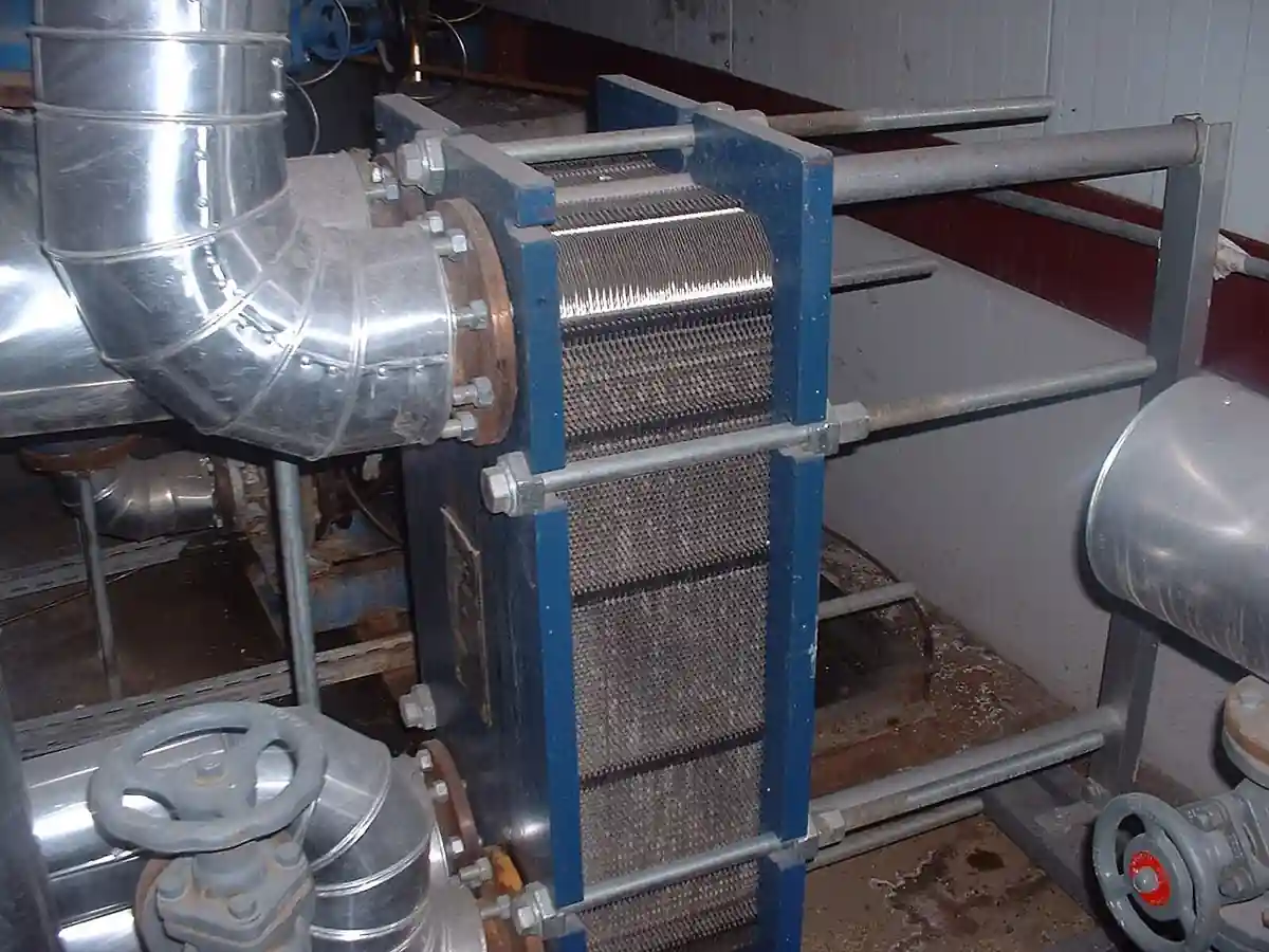
A plate-fin heat exchanger is a compact heat exchanger built as a stack of flat parting sheets separated by corrugated fin layers, all joined into a single vacuum brazed aluminum block with headers welded on, so that two or more streams exchange heat through an enormous secondary heat transfer surface packed into a small volume. Multi stream cores handling three, four, or more streams in one block are routine, which is why the technology dominates cryogenic gas processing: air separation plants, LNG liquefaction and peak shaving, ethylene cold sections, and hydrogen and helium purification all run on brazed aluminum cores, usually stacked inside insulated cold boxes. Chart Industries catalogs brazed aluminum heat exchangers of this class as core process equipment, and this page treats the core and its cold box integration as the purchasing object.
This page is written for the process engineer specifying plate-fin heat exchangers for cryogenic or clean gas duty. It works through what the brazed core actually does and what is being bought, how fin geometry and layer stacking build the heat transfer, which core configurations fit which duties, the parameters that appear on manufacturer data sheets, and the selection factors and RFQ language that decide whether the core delivers its duty for a thirty year life.
The decision concentrates in five places: the streams and their duty envelope, flow, pressure, temperature, and phase change; the fin geometries and layer stacking that build area and pressure drop; the header and distributor design that keeps flow even across every layer; the aluminum materials envelope, clean fluids and temperature limits; and the cold box and installation context that the core must survive. Get those right and the core dimensions, nozzle loads, and support design follow.
Chapter 1 / 06
What a Plate-Fin Heat Exchanger Is and What Is Being Decided
The machine this page describes is a brazed aluminum block exchanger. Its anatomy repeats one sandwich: a parting sheet, a layer of corrugated fins, another parting sheet, then a fin layer carrying a different stream, and so on for hundreds of layers. The corrugated fins act as secondary surface, multiplying heat transfer area several fold per unit volume over a shell and tube design, and as structural spacing that carries pressure load between parting sheets. Half meter wide cores run common, and blocks assemble in banks over a meter thick; headers and nozzles welded to the block faces collect each stream, and the finished core is pressure tested, dried, and shipped for installation, usually suspended inside a cold box filled with perlite insulation.
What is being decided when a plate-fin heat exchanger is purchased is a thermal duty and pressure envelope guaranteed for decades in a machine that cannot be mechanically cleaned. The buyer is purchasing multi stream heat exchange with approach temperatures down to 1 to 3 degrees C, pressure drops held to design on every stream, and leak tightness between streams over a 20 to 30 year life, all in aluminum whose chemical and temperature envelope must be respected from day one. Everything on the manufacturer data sheet, core dimensions, layer counts, fin types per stream, design pressure and temperature, nozzle sizes and loads, exists to support those guarantees, and the honest vendor thermal rates the core from stated fluid properties and defends the layer by layer distribution.
The plate-fin core sits in the heat exchanger family with defined neighbors. It is not the gasketed or welded plate heat exchanger of low pressure liquid service, whose corrugated plates clamp or weld into a frame; the live plate heat exchanger page covers that family, and it has no plate-fin core inside. It is not a shell and tube heat exchanger, the tube bundle workhorse that tolerates fouling and high pressure at far lower area density. It is not an air-cooled heat exchanger, which rejects heat to ambient air with fin fans. And it is not a printed circuit heat exchanger, the chemically etched diffusion bonded alternative that serves higher pressures; that neighbor stays outside this page's scope. The plate-fin core wins where cryogenic temperature approach, multi stream integration, and compactness align.
Different buyers buy the same core for different reasons. An air separation plant buys it as the main vaporizers, liquefiers, and subcoolers that make an ASU a cold machine at all, integrating oxygen, nitrogen, and argon streams in one block. An LNG peak shaver or liquefaction plant buys it as the main cryogenic exchanger threading natural gas, refrigerants, and boil off through one core. An ethylene plant buys it for the cold section around the turboexpander and the demethanizer. A hydrogen or helium purification train buys it for low temperature recovery around the cryogenic separator. The specification language differs, but the fin physics is shared.
The economics deserve their own paragraph because the core's price is justified by integration, not by area alone. Against a shell and tube alternative on the same cryogenic duty, the plate-fin core costs more per kilogram and far less per installed function: one block replaces multiple shells, elbows, and supports; approach temperatures tighten and compression power falls; and the cold box shrinks the footprint and the insulation volume. Against those stand real constraints: the core is aluminum, with a mercury and water and CO2 sensitivity that demands rigorous upstream cleanup, and it cannot be rodded or brushed clean, so fouling service is disqualifying. The honest comparison prices the cleanup train and the compression savings together, not the exchanger alone.
A short tour of named duties makes the core concrete. In an ASU, the main heat exchanger cools incoming air against returning oxygen and nitrogen products within 2 degrees C approach, all in one multi stream block. In a peak shaving LNG plant, natural gas liquefies against a mixed refrigerant loop through a core stacked beside a turboexpander compander train. In an ethylene cold box, cracked gas chills to the demethanizer while methane and hydrogen streams rewarm. At a hydrogen purification unit, feed chills to condense methane and nitrogen impurities around a liquid nitrogen bathed core. Each duty names the same knobs, fin selection, layer count, distribution, and materials envelope, with numbers that scale while the brazed sandwich barely changes.
Chapter 2 / 06
How the Fins and Layers Do the Work
The corrugated fin is the heart of the machine. Plain, perforated, serrated, and herringbone or wavy fins trade heat transfer against pressure drop: serrated fins interrupt boundary layers and run the highest coefficients at the highest pressure drop per meter; plain fins run the lowest pressure drop for condensing and low pressure streams; perforated fins distribute two phase flows and improve boiling stability; herringbone fins sit between. Fin height and thickness set the free flow area and the secondary area per layer, and the designer picks a fin per stream much as a pump engineer picks an impeller, matching the stream's pressure drop budget to its heat transfer duty.
Layer stacking turns fins into a machine. Each stream is assigned a number of layers and a place in the stack, and the stacking alternates streams so that heat crosses the parting sheets efficiently and thermal stress stays balanced; a boiling layer sits against condensing or single phase layers deliberately, and adjacent same stream layers are avoided unless duty demands them. Distributor fins, diagonal or perforated transition sections, spread flow from the header across the layer width, and their design is where maldistribution is won or lost. The finished stack is brazed in a vacuum furnace, parting sheets, fins, and seal bars fusing into one monolithic block, and the headers weld on afterward for full penetration strength.
Brazing discipline is the manufacturing core competence and the buyer's quality leverage. Core assemblies are clamped, fluxless vacuum brazed at temperature in large furnaces, and the result is thousands of joints per layer made simultaneously; a braze that misses leaves internal leakage paths that only a rigorous test regime catches. Manufacturers proof test every core hydrostatically or pneumatically to design conditions, and leak test between streams at sensitivity levels appropriate to the service, oxygen or hydrocarbon, before shipment. The purchase specification should demand the test procedure, pressures, and acceptance, and for oxygen service the cleaning and contamination controls that cryogenic oxygen duty requires.
The materials envelope sets hard boundaries that the process design must respect. Cores are aluminum alloys, 3003 class fin and sheet with 5083 headers in common practice, strong at cryogenic temperature and limited at the top end, with design temperatures commonly capped near 65 to 70 degrees C by the manufacturer's allowable stress basis, though some designs rate higher; mercury attack and alkaline water attack on aluminum are the classic chemical killers, so mercury removal beds guard LNG feeds and drying to specification is absolute. Design pressures span from a few bar for atmospheric column service to 100 bar class for high pressure streams, with the parting sheet thickness and layer width setting the ceiling. Clean, dry, non corrosive fluid is the entry ticket.
Two phase and phase change duties add the distribution problem. Boiling layers must see even two phase feed across the width or the layer dries out locally and freezes or fouls; condensing layers must drain without liquid holdup blanketing area. Diagonal distributor fins, two phase feed nozzles with phase separation and recombination, and vertical orientation choices, boiling up or down flow per the duty, are the designer's tools, and the buyer's protection is the vendor's two phase distribution experience on comparable plants. A plate-fin core with maldistribution is not a smaller exchanger, it is a damaged one, because local dryout in a freezing service plugs layers irreversibly.
Cold box integration is where the core becomes a plant. Cores suspend on support angles inside a carbon steel box, with stainless to aluminum transition piping at the nozzles handling differential contraction, and the box purged then filled with perlite or foamed insulation to kill convection; piping loads on the nozzles are limited by design because aluminum headers are not structural anchors. Warm ends, cold ends, and intermediate nozzles route through sleeves, and the pipe stress model must include the core as a stiff block with allowed loads. The cold box is part of the exchanger purchase in most packages, and drawing its boundary explicitly is a classic RFQ scope item.
Chapter 3 / 06
Core Types, Cold Box Integration, and Duty Boundaries
Configuration choice begins with the stream count and the phase duties. Two stream cores serve simple interchangers; multi stream cores, the majority of cryogenic service, integrate three to six streams in one block by alternating layers, replacing whole networks of shells. Banks of cores bolt in parallel for large duties, sharing headers and distributing flow between blocks. Orientation follows phase change: boiling and thermosiphon layers favor vertical cores with flow direction chosen by the duty, condensers favor downflow or horizontal, and pure gas to gas interchangers run vertical by cold box convention. Header arrangements, single or double banking, and nozzle locations come from the piping layout around the box.
Configuration
Typical service
Character
Two stream core
gas to gas interchanger
Simplest, one duty per block
Multi stream core
ASU main exchanger
3-6 streams, network in a block
Parallel core bank
large LNG liquefier
Duty beyond one block width
Thermosiphon core
boiling refrigerant layer
Vertical, distribution critical
Core in cold box
any cryogenic duty
Perlite insulated, suspended
Duty boundaries keep the technology honest. Fouling fluids, dirty gas with compressor oil carryover, dust, or pipeline debris, disqualify the core because there is no cleaning access; upstream filtration and adsorption guard the machine. Fluids attacking aluminum, mercury in natural gas, alkaline water washes, high chloride brines, are excluded by process design, with molecular sieve dehydration and mercury guard beds upstream of LNG cores standard. High pressure above roughly 100 bar class and temperature above the aluminum envelope push duty to printed circuit or shell and tube alternatives. Within its boundaries the core is the most compact multi stream cryogenic machine available.
Where it sits in the plant matters as much as the core. Upstream, dryers and guards, a molecular sieve dehydrator for water and carbon dioxide removal ahead of LNG or ASU cold sections, and mercury removal beds, set the feed quality the core depends on; a knockout drum protects against liquid slugs from warm piping. Downstream, the products leave through the cold box warm end to compression or storage; a turboexpander sits inside the same box in most liquefaction and expander plants, its loads tied into the same piping model; and cryogenic valves, cryogenic ball valve classes at block points, share the low temperature materials discipline. The core is bought as part of a cold machine, never as an isolated blob of aluminum.
Scale and delivery shape the commercial choice too. Cores are built to order with engineering and brazing lead times measured in months, and very large duties ship as core banks assembled on site inside the box; standardization programs from the major manufacturers shorten delivery for common ASU and peak shaver sizes. Repair economics differ from shell and tube: a leaking internal layer cannot be re tubed, and the practical remedies are layer isolation, where the design allows spare layers, or block replacement, so critical services buy margin layers or parallel banks from day one. That lifecycle arithmetic belongs in the selection, not after the first leak.
Chapter 4 / 06
Key Specification Parameters
The data sheet parameters fall into four groups: thermal, hydraulic, mechanical, and integration. Thermal parameters are the duty per stream, terminal temperatures, and approach, with the fluid basis stated; hydraulic parameters are design and operating pressure drops per stream at rated flow; mechanical parameters are design pressure and temperature per stream side, core dimensions and weight, materials of sheets, fins, and headers, and the code basis; integration parameters are nozzle sizes, orientations, and allowable loads, support type, and cold box scope. A quotation that omits per stream pressure drop or nozzle allowable loads is not comparable to one that states them.
Parameter
Typical range
Design note
Core width
up to ~1.2 m
Banks parallel beyond that
Core stack thickness
up to ~1.2 m
Layer count sets it
Design pressure
to ~100 bar class
Parting sheet and width bound it
Design temperature
-269 to +65 C class
Alloy allowable stress cap
Approach temperature
1-3 K cryogenic
The compactness payoff
Fin types per stream
plain to serrated
Heat transfer vs dP choice
Streams per core
2-6
Network in one block
Layer counts
per stream duty
Distribution and margin
Test regime
strength + leak per stream
Oxygen cleaning where applicable
Approach temperature and pressure drop deserve explicit numbers in every specification because they set the plant's power bill. Every degree of warm end approach in an ASU main exchanger is compression work lost to the cold machine; the core's compactness buys 1 to 3 degree approaches that shells cannot reach economically, and the specification should state the approach guarantees with their basis. Per stream pressure drop budgets come from the process model, and the vendor should quote guaranteed drop at rated flow, because a core that meets thermal duty while blowing the pressure budget starves the downstream turboexpander or column.
Standards ride the manufacturing and test side. Brazed aluminum cores are built to manufacturer standards audited against pressure vessel code practice, with ASME VIII or equivalent design basis for the pressure parts, and the industry's own standards for brazed aluminum plate-fin heat exchangers, ALPEMA, govern dimensions, tolerances, installation, and handling practice. Cryogenic oxygen service adds cleaning and contamination controls; LNG and hydrocarbon service adds the leak test sensitivity discussion; and transport, with core crate integrity and nitrogen purge holding, is part of the standard's scope. An RFQ should name the code basis, the test acceptance, and the handling standard rather than assume them.
Allowable nozzle loads and support design round out the sheet. Aluminum headers accept far less piping load than steel shells, so the pipe stress model must respect the vendor's allowable load table at temperature, and stainless transition spools absorb differential contraction between core and external piping. Supports suspend the core in the box with clearance for contraction on cooldown; restraints during transport are engineered and their removal at installation is a checklist item. The number of cores killed by pipe loads and restraint mishandling exceeds the number killed by process upsets, which is why the ALPEMA installation practice exists at all.
Chapter 5 / 06
Selection Decision Factors and RFQ Language
Selection starts from the stream table and the cleanliness story. The designer writes every stream with flow, composition, pressure, and temperature envelope, phase duties, and the target approach and pressure drop; then the feed cleanup train, dehydration, carbon dioxide and mercury removal, and filtration, that qualifies each stream for aluminum; then the integration context, cold box scope, turboexpander interface, and plot. From that basis the vendor builds layer counts and fin selections, and competing offers are compared layer by layer, not price by price. An RFQ without the cleanliness story invites a vendor to assume one.
Distribution and freeze margin are the second decision axis and the one that separates vendors. Every cryogenic core risks local freezing of the highest freezing point species, carbon dioxide, water, heavy hydrocarbons, and the design holds wall temperatures above the freeze curve with stated margin; two phase feeds need distributor designs with referenced plant experience. The buyer should ask for the freeze margin analysis on the actual composition, the two phase distribution references, and what happens on the anticipated upset, a warm end excursion, a slug, a trip, because the answer describes how the core ages. Vendors who answer with layer counts alone have not answered.
The RFQ language that returns comparable offers states the stream table and the guarantees demanded. State each stream's flow, composition, pressure, and temperature range with phase change points, the duty and target approach, allowable pressure drop per stream, design pressure and temperature per side, materials and test requirements with the code basis, nozzle allowable loads the vendor must design against, cold box scope and insulation, installation standard practice to follow, and the delivery and transport purge requirements. A complete RFQ paragraph reads: 3 stream core, feed 120000 Nm3/h natural gas at 40 bar chilling from 30 to -150 C against returning LNG and refrigerant streams, approach within 3 K, CO2 below 50 ppm by upstream sieve, design 60 bar, cold box by vendor to ALPEMA installation practice.
Commercial comparison is only fair on a normalized basis. Offers should be forced onto one table: guaranteed duty, approach, and pressure drop per stream at stated flows; design pressures and temperatures per side; materials and fin types proposed; layer counts and spare or margin layers; test pressures, procedures, and leak sensitivity; nozzle allowable loads; cold box scope; delivery and transport arrangements; and references on the same fluid and phase duty. The cheapest core is very often the one with the thinnest freeze margin and the least distribution experience, and its life cycle cost lands at the first plant upset.
Lifecycle questions close the selection. What margin layers or parallel banks protect the duty against a single internal leak; what monitoring, differential pressure per stream and temperature profile, reveals a plugged or leaking layer early; what the repair path is, layer isolation or block replacement, and its lead time; and how the core ships and holds its nitrogen purge to site. A plate-fin purchase is a thirty year commitment inside an insulated box that is expensive to open, and these questions are cheap to ask before award.
Integration utilities finish the selection table because the core never runs alone. Cold box feed arrives from compression, a screw compressor or a centrifugal compressor train upstream depending on scale, and the driver economics, soft start or a variable frequency drive on the motors, belong in the same energy model as the core's approach guarantee. The warm side ties to the site steam system through waste heat recovery, where a steam drum closes the boiler circuit and a reboiler elsewhere in the process may share the same heat source; startup and trip vents route to the flare stack under the plant's safety philosophy, and the battery limit metering on each stream, a flow meter per line with cryogenic compensation, is what makes the performance test arguable. These items are rarely on the exchanger vendor's scope, which is exactly why the RFQ must name them: the core is an aluminum block, but the plant around it is where projects are won and lost.
Chapter 6 / 06
Installation, Standards, Failure Modes, and Maintenance
Installation follows the manufacturer's practice to the letter. The core arrives purged with nitrogen under a holding pressure, and the purge integrity is verified before anything else; transport restraints come off in the documented order; the core suspends in the box on its support angles with contraction clearance; stainless transition spools and piping land within the allowable load table; and the box closes, purges, and fills with dry perlite only after leak testing of the assembled circuits. Cooldown is a controlled ramp, commonly limited to a stated rate of tens of degrees C per hour, so thermal gradients through the block do not overstress braze joints. Skipping the cooldown discipline is the classic way to turn a healthy core into a leaking one.
Failure modes have a known hierarchy, and almost all are process discipline failures rather than braze failures. Freeze plugging, from carbon dioxide or water breakthrough of the upstream dryers, blocks layers and shows as rising pressure drop and shifting temperature profiles; mercury attack corrodes aluminum braze joints over months and leaks; alkaline or chloride bearing washes attack the metal; thermal shock from fast cooldown or warm slugs cracks joints; and pipe load or restraint stress cracks headers and nozzles. Genuine internal leaks announce themselves as stream contamination, product purity drift in an ASU, warm end mismatch in an interchanger, and are confirmed by cross stream analysis.
Symptom
Likely cause
First response
Rising dP one stream
freeze plug layers
Check dryers, warm slowly if safe
Product purity drift
internal leak
Cross stream analysis, plan isolation
Temperature profile shift
maldistribution or plug
Profile survey vs design
Warm end approach growth
fouling or leak
Feed audit, contamination test
Nozzle or header crack
pipe load or shock
Stress model review, repair weld
Maintenance is protection rather than intervention, because the core cannot be opened. Upstream cleanup train discipline, differential trends on the molecular sieve dehydration beds and mercury guards, is the core's real maintenance program; per stream pressure drop and temperature profile trends catch a plug or leak years before it stops the plant; and periodic perlite condition and box purge checks keep insulation performance honest. Where a leak does occur, options are layer isolation where the design provided spare layers, stream rerating, or block replacement as a planned project with its months of lead. The differential trend sheet is the machine's stethoscope.
Operational stewardship is what the purchase actually bought. Hold the cooldown and warmup ramps to the manufacturer's curve, protect the dryers and guards as the core's immune system, keep liquid slugs and oil carryover out of the warm end, and trend every stream's pressure drop and temperature profile against commissioning baselines. Plants that respect the aluminum, clean feed, gentle ramps, honest trends, run brazed cores for three decades; plants that treat the core like a steel shell buy themselves an unplanned cold box opening, and no one who has opened one recommends it.
FAQ
What is the difference between a plate-fin and a plate heat exchanger?
A plate-fin heat exchanger is a vacuum brazed aluminum block of parting sheets and corrugated fin layers for cryogenic, clean, multi stream gas service, while the plate heat exchanger family is corrugated plates, gasketed or welded, for liquid to liquid duty at moderate pressure. The two share the word plate and almost nothing else: different geometry, different pressure and temperature envelopes, different fluids. Cryogenic gas plants buy plate-fin cores; hot water and HVAC duty buys plate exchangers.
Why is vacuum brazing used for plate-fin cores?
Because the fin to parting sheet joints, thousands per layer across hundreds of layers, must all be made at once with no flux residue in oxygen or cryogenic service. The assembled stack is furnace brazed under vacuum so aluminum filler flows and fuses every fin foot to its sheets, producing one monolithic pressure containing block. Braze discipline is the manufacturer's core competence and the reason core quality is vendor experience dependent.
Can a plate-fin heat exchanger handle more than two streams?
Yes, that is its defining strength. Layers carrying different streams alternate through the stack, and headers segregate each stream, so one block integrates three to six streams that would otherwise need a network of two stream exchangers, elbows, and supports. Air separation main exchangers and LNG liquefier cores are the classic multi stream applications.
What fluids must be kept out of a brazed aluminum core?
Water and carbon dioxide above their freeze limits plug layers at cryogenic temperature, which is why molecular sieve dehydration sits upstream; mercury attacks aluminum braze joints and needs guard beds on natural gas; alkaline solutions and high chloride waters corrode aluminum; and compressor oil or particulate fouls the fine fin passages permanently. The core is a clean fluid machine and the upstream cleanup train is part of its purchase.
What design pressure and temperature can a plate-fin core take?
Design pressures commonly run to the 100 bar class with parting sheet thickness and layer width setting the ceiling, and design temperatures span from near absolute zero, where aluminum is strong and tough, up to roughly 65 degrees C on the standard allowable stress basis, with some designs rated higher. Above those envelopes, duty moves to printed circuit heat exchangers or shell and tube designs. Each stream side carries its own design pressure in the data sheet.
How tight an approach temperature can it achieve?
Approaches of 1 to 3 degrees C are routine in cryogenic service because the fin secondary surface packs so much area into the block, and that tightness is the economic heart of the technology: every saved degree of warm end approach in an air separation or LNG plant is compression power saved. Competing offers should be compared on guaranteed approach with the basis stated, because it moves the plant power bill more than the exchanger price.
What happens if a plate-fin core develops an internal leak?
A leak between layers shows as stream contamination, drifting product purity or a warm end mismatch, confirmed by cross stream analysis. Because the block cannot be opened, remedies are layer isolation if the design provided spare layers, rerating streams around the leak, or block replacement inside the cold box, a planned project with months of lead. This lifecycle reality is why critical services buy margin layers or parallel banks, and why per stream pressure drop and temperature trends are watched like vital signs.