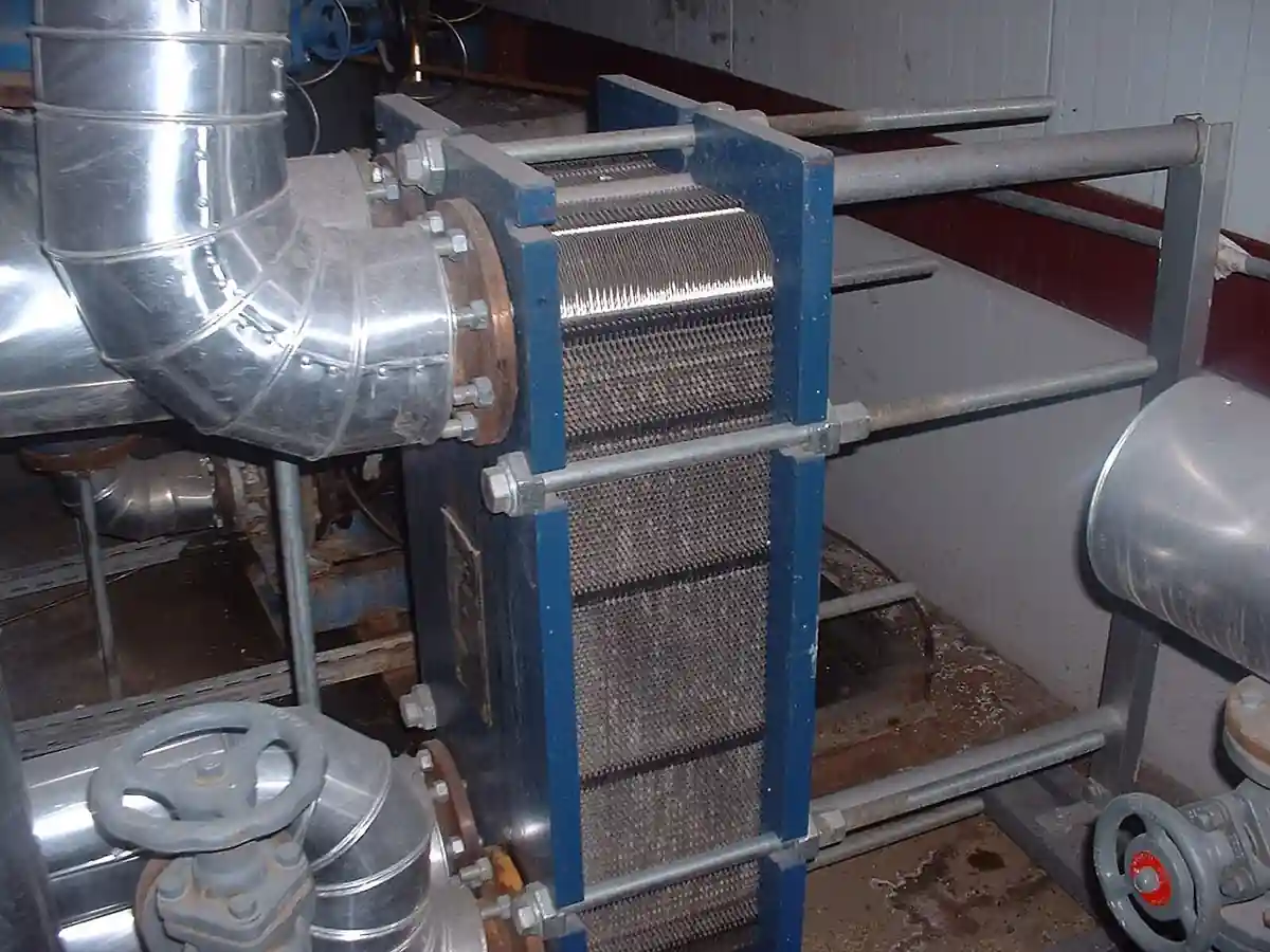
A feedwater heater is a closed, shell-and-tube heat exchanger that raises the temperature of water on its way to a boiler, a heat recovery steam generator, or a nuclear steam generator, using steam extracted from the turbine as the heat source, so the cycle burns less fuel for the same power. Feedwater flows through the tubes while extraction steam condenses on the shell side, and most heaters arrange three zones in one shell, a desuperheating zone that recovers superheat, a condensing zone that does the bulk of the duty, and a drain-cooling zone that subcools the condensate before it cascades onward. Low-pressure heaters sit between the condensate system and the deaerator; high-pressure heaters sit between the deaerator and the boiler on the boiler feed pump discharge. Babcock Power's heater literature and Thermal Engineering International's heat transfer guides are representative industrial references, and this page treats the complete exchanger, channel, bundle, and drain trim, as the purchasing object.
This page is written for the engineer specifying closed feedwater heaters for a fossil unit, a combined-cycle plant, or a replacement program on an aging fleet. It works through what the machine does and what is being bought, how the zones and the terminal temperature difference define performance, which heater architectures fit which cycle positions, the parameters that appear on vendor data sheets, and the selection factors and RFQ language that decide whether the heater holds its heat rate contribution for a service life measured in decades.
The decision concentrates in five places: the extraction steam states available at each stage, the feedwater flow and the temperature rise the cycle asks of each heater, the zone arrangement, desuperheater and drain cooler or plain condensing, the terminal temperature difference and drain approach the vendor will guarantee, and the construction, channel type, tube material, and code stamp, that survives the pressure and the decades. Get those right and the drains, vents, and level controls follow with little freedom.
Chapter 1 / 06
What a Feedwater Heater Is and What Is Being Decided
The machine this page describes is a cylindrical shell, steel, code stamped, carrying a tube bundle of straight or U-bent tubing between one or two tube sheets, with a channel head, hemispherical on high-pressure heaters, that routes feedwater into and out of the tubes and holds the pass partitions. Extraction steam enters the shell through a nozzle sized for the stage flow, desuperheats against the outlet end of the bundle, condenses over the main surface, and the condensate level in the shell bottom is controlled so a drain-cooling zone can subcool it before it leaves. In a power plant cycle the heaters stand in a train, condensate from the surface condenser through the low-pressure heaters to the deaerator, then feedwater from the boiler feed pump through the high-pressure heaters to the steam generator.
What is being decided when a feedwater heater is purchased is a feedwater temperature and a heat rate contribution backed by a duty and pressure statement. The buyer is purchasing a stated outlet temperature at a stated feedwater flow from a stated extraction pressure and condition, with a terminal temperature difference and a drain subcooling the vendor will guarantee, in a vessel that holds the full feedwater pressure for the plant's life. Everything on the vendor data sheet, surface area, zone lengths, tube count and gauge, nozzle sizes, exists to support those guarantees, and the honest vendor quotes the zone by zone thermal design, not only the total surface.
The feedwater heater sits in the power cycle family with defined neighbors. It is a closed exchanger: the extraction steam and the feedwater never mix, which is what separates it from the deaerator, the direct contact vessel that removes dissolved oxygen by scrubbing the water with steam, a different machine this encyclopedia treats in its own page and one every closed heater train passes through. It is not the economizer, the flue-gas-to-feedwater exchanger in the boiler backpass that recovers stack heat rather than cycle heat, and it is not the surface condenser, which exhausts the turbine against cooling water rather than heating feedwater. All of them are shell-and-tube heat exchanger geometry doing different cycle jobs, and the family page covers the generic construction while this page covers the extraction heater specifically.
Different buyers buy the same machine for different cycles. A coal or gas fossil unit buys a train of low-pressure and high-pressure heaters on a regenerative Rankine cycle, valuing heat rate and availability. A combined-cycle plant buys heaters fed from the steam turbine of its bottoming cycle, often fewer and larger, integrated with the heat recovery steam generator's feed arrangement, and the HRSG's own economizer panels neighbor the duty. A nuclear plant buys high-pressure heaters of exceptional size and code class feeding steam generators, where tube integrity and inspection access govern. Industrial cogeneration plants buy single heaters off backpressure or extraction turbines for process and boiler feed duty. The specification language differs, but the condensing zone physics is shared.
The economics deserve their own paragraph because regenerative feedwater heating is why the Rankine cycle is competitive. Every degree of feedwater temperature bought with extraction steam is fuel not burned in the boiler, and a typical multi-stage train moves final feedwater temperature by a large margin over condensate temperature, worth a few percent of unit heat rate; a heater bypassed or failed out of service shows up on the plant's fuel bill within the day. Against that stand the costs: heater capital, the extraction steam's lost work, and the maintenance of a pressure vessel on the feed line whose failure can threaten the boiler. The selection is therefore a cycle decision first and a vessel decision second, and the RFQ should arrive with the cycle's answer already in it.
A short tour of named positions makes the machine concrete. On a supercritical coal unit, four low-pressure heaters in the condensate line take extractions from the low-pressure turbine, the deaerator sits on an intermediate extraction, and two or three high-pressure heaters on the feed pump discharge take extractions from the high-pressure turbine, delivering final feedwater to the economizer inlet. On a combined-cycle block, one or two HP heaters fed from the steam turbine raise the HRSG feed temperature. On a naval or industrial boiler, a single heater off an auxiliary exhaust feeds the deaerator in cascade. Each position names the same knobs, extraction state, zone arrangement, TTD, and drains, with pressures and sizes that scale while the condensing physics barely changes.
Chapter 2 / 06
How the Zones and the Terminal Temperature Difference Do the Work
The condensing zone is the engine. Steam condensing on the outside of the tubes transfers heat at high coefficients, and the zone is sized so the steam saturates and condenses over most of the bundle length at essentially constant temperature. Feedwater in the tubes heats along its length toward that saturation temperature, and the gap it can never quite close, the difference between the steam's saturation temperature at the extraction pressure and the feedwater outlet temperature, is the terminal temperature difference, TTD, the single most quoted performance number on the data sheet. Small TTD means more surface, or better bundle hydraulics, and a few degrees of TTD are worth real money in heat rate.
The desuperheating zone recovers the superheat that high-pressure extrations carry. Steam enters a shrouded section of the bundle at the outlet end, gives up its superheat to the already hot feedwater, and only then enters the condensing zone; the zone is a counterflow exchanger inside the shell, with baffles supporting long tube spans. Done well it lifts the outlet temperature above what saturation alone would give, and some heater designs quote negative TTD against the saturation temperature because the desuperheater carries the water past it. Done poorly, excess superheat reaches the condensing zone and wastes surface, so the zone split is a genuine design decision the buyer should see.
The drain-cooling zone subcools the condensate. The accumulated drains, this heater's own condensate plus whatever cascades in from the heater above it, pass through a flooded section of bundle at the feedwater inlet end, leaving heat against the coldest water and exiting subcooled, a few degrees above the feedwater inlet temperature if the zone is honest. The drain approach, like the TTD, is a guaranteed number. Without the zone, drains flash in the cascade line and the next lower heater receives steam with its water, wasting capacity; with it, the cascade is quiet water all the way down to the condenser or the deaerator.
Drains and vents are the hydraulics that keep the zones honest. Each heater's condensate level is held by a level controller, from a drain valve to the next lower pressure point or to a drain pump on the end of the train, and the setpoint balances the drain cooler's flooded length against the risk of flooding the condensing surface. Noncondensable gases, air and oxygen that rode in with the steam or leaked in, collect under the shell and blanket heat transfer, so continuous venting, small lines from the shell to the condenser or the next heater, purges them. A heater with a failed vent or a mis-set level loses performance quietly, which is why level and vent instrumentation belong on the heater scope, not on a plant afterthought list.
Feed-side hydraulics matter as much as steam side. Feedwater in the tubes at boiler feed pump pressure, on HP heaters the full system pressure, must flow at velocities that balance heat transfer against erosion and pressure drop, and pass partitions in the channel set the number of tube passes. High pressure heaters on large units feed in series, and the loss of one to a tube leak forces the train into bypass with a heat rate penalty and a feedwater temperature drop the boiler notices. The channel design, manways, pass partition gaskets, and the bundle pull clearances, decides whether inspection is a shift or an outage.
Performance degradation has a short honest list. Tube fouling on the feed side, oxide and deposits, raises TTD slowly over years and responds to chemical cleaning. Air binding from failed vents blankets surface fast. Tube leaks, from erosion at baffles, corrosion at supports, or vibration fatigue, put water in the shell, raise level, and force the heater out of service; detection is level and chemistry, location is by half-bundle isolation or eddy current at the outage. None of these are exotic, but all of them are why the construction standards, tube material, support spacing, and inspection access, are worth their price at purchase time.
Chapter 3 / 06
Heater Types, Cycle Positions, and Machine Boundaries
Low-pressure heaters serve the condensate line. They take extractions from the low-pressure turbine at sub-atmospheric to modest pressures, run feedwater at condensate pump pressure, and are built as channel-head shell-and-tube exchangers, often horizontal on fossil units, with two or four tube passes. Their shells run vacuum to low positive pressure, their duty is moderate, and they are usually channel and bundle construction so a bundle can be pulled and serviced without cutting the shell. Sizes run from small industrial units to the very large LP heaters of nuclear trains.
High-pressure heaters serve the feed pump discharge. They take extractions from the high-pressure turbine at high pressure and temperature, run feedwater at full system pressure, and are built heavier in every dimension: hemispherical or deeply dished channel heads, thick tube sheets, U-tube bundles that tolerate the thermal growth, and forged nozzles. The U-tube is the default because it absorbs differential expansion without an expansion joint, and its mechanical simplicity is why HP heaters last decades. Horizontal mounting dominates for drain handling and pull access, though vertical HP heaters serve plants with tight layouts and marine plants.
Zone arrangements name the variants within each class. A plain condensing heater, one zone, suits saturated or modestly superheated extractions at the LP end. Desuperheating-condensing heaters add the shrouded counterflow section for hot extractions. Full-zone heaters, desuperheating, condensing, and drain cooling in one shell, are the standard HP machine. Split or twin-shell arrangements parallel two shells on one stage for maintainability at large flows, letting a plant run half the stage while the other half is opened, and cascade arrangements chain drains from higher to lower heaters, finishing in the condenser hotwell or a drain cooler.
Deaerating heaters, the direct contact column integral with a storage tank, blur the boundary on purpose: they are the deaerator's own machine, mixing steam and water to strip oxygen, and every regenerative train passes through one between the LP and HP sections. This page's machine is closed, no mixing, and the difference matters to the buyer because the closed heater's failure modes are vessel and tube issues while the deaerator's are chemistry and storage issues. Compact alternatives exist at the edges: in some high-pressure gas and nuclear applications etched-plate diffusion-bonded cores, the printed circuit heat exchanger family, carry feed or extraction duties at conditions beyond conventional tubing, and they are treated in their own page rather than here.
Adjacent machines mark the rest of the boundary. The economizer heats the same feedwater with flue gas in the boiler or heat recovery steam generator backpass, fired on a combined-cycle block by the gas turbine exhaust, and is not this machine, though the two share the outlet line and the cycle drawing. The surface condenser condenses the exhaust end of the turbine against cooling water from the cooling tower or once-through source, its vacuum held by a steam ejector or a vacuum pump. The superheater and the steam drum live on the boiler side of the wall. The aftercooler of the station air system shares nothing but the word cooler, and compact brazed cores in the plate fin heat exchanger family serve cryogenic and gas duties rather than feedwater. Within the heater's own family, the differences are class and zone, not species, and the RFQ should state stage, extraction state, and zones rather than asking for a feedwater heater and hoping.
Chapter 4 / 06
Key Specification Parameters
The vendor data sheet for a feedwater heater centers on duty, TTD, drain approach, and the pressure parts, and each number carries a cycle consequence. The table below lists the parameters that recur across manufacturers' catalogs, with typical ranges for power plant service; values for a specific project come from the cycle heat balance and the vendor's zone design, and the ranges here are orientation, not a substitute for the cycle.
Three of these numbers deserve the buyer's suspicion when they arrive without a basis. A TTD quoted without stating whether it is against the desuperheater outlet or the saturation temperature flatters the design by degrees the cycle will not see. A drain approach quoted without the cascade flow it assumes ignores the heater above contributing its drains. Surface area quoted as a single total hides the zone split, and two heaters of equal area can differ by a zone's worth of feedwater temperature. An RFQ that asks for the zone by zone design summary separates engineered offers from assembled ones.
Materials follow the water chemistry and the stage. Carbon steel tubing serves standard fossil chemistry with all-volatile treatment; stainless grades and copper alloys appear where chemistry or cooling water in-leakage history argues for them; titanium and superferritic grades serve nuclear and seawater-cooled plants where anything less fails. Tube sheets are forged, channel heads hemispherical on HP shells, and supports spaced against flow-induced vibration with the tube spans the zone baffling creates. Impingement protection under the steam nozzle, drain weir and level instrumentation taps, and vent connections complete the shell, and their presence in the quote is a quick test of whether the vendor has built this machine before.
Chapter 5 / 06
Selection Decision Factors and RFQ Language
Selection starts with the cycle, not the catalog. The heat balance fixes each stage's extraction pressure and flow, the feedwater flow and inlet temperature, and the target outlet temperature that sets the heat rate; the buyer's freedom is in how many stages, which zones, and what construction. Fewer larger heaters simplify the train; more stages squeeze heat rate at the cost of piping and maintenance points. The decision belongs to the cycle engineer, and the heater RFQ should arrive with the stage duty table already frozen, because a vendor asked to assume the cycle will assume it wrong.
The construction choice follows pressure, chemistry, and the plant's outage philosophy. Channel-and-bundle construction everywhere service access matters; welded or full-penetration designs where leak-before-burst behavior and code class dominate. Split-shell or two-shell parallel arrangements where half-stage operation must survive an outage. Tube material against the water treatment program the plant actually runs, not the one its manual describes. Pull clearances, manways, and eddy current access decide whether a tube leak costs a day or a month, and they are worth their price on the first forced outage.
The table below organizes the decision into the factors that recur across projects, with the questions the buyer should be able to answer before the RFQ goes out. Each row is a place where an incomplete answer turns into an underspecified vessel and a heat rate argument later.
Decision factor
What the buyer must state
Consequence if left open
Cycle position
Stage, LP or HP, extraction pressure and condition, drains cascaded in
Zone design wrong; TTD basis ambiguous
Duty and flow
Feedwater flow, inlet and required outlet temperature, TTD guarantee basis
Heat rate contribution unverified
Pressures and codes
Tube-side design pressure and temperature, shell side, code jurisdiction
Vessel class wrong; requote or rerate later
Water chemistry
Treatment program, dissolved oxygen at inlet, chemistry excursions history
Tube material mismatch; premature failure
Layout and access
Horizontal or vertical, pull clearances, manway and inspection access
Level controls, vents, drains valves, instrumentation in heater scope or not
Commissioning gaps between packages
RFQ language for a feedwater heater should name the stage and the basis of guarantee. A workable specification states: cycle position and extraction state with the heat balance reference; feedwater flow with inlet temperature and required outlet temperature at stated TTD basis; drain approach and cascade flows; tube-side and shell-side design conditions with the applicable pressure code; zone arrangement required; tube material and support spacing philosophy; construction, channel type and bundle arrangement, with access provisions; level control, vent, and drain scope; and the acceptance basis, witnessed hydrotest, and a performance route agreed for TTD verification at commissioning. Naming the neighbors fixes the interfaces, the deaerator upstream, the economizer or the heat recovery steam generator receiving the heated feed, the boiler feed pump and the condensate return pump setting the hydraulics, so the nozzles and the guarantees land in the right bids.
Chapter 6 / 06
Installation, Standards, Failure Modes, and Maintenance
Installation is a pressure vessel job with a cycle tie-in at the end. Foundations and saddles set the shell with the slope the drain design assumes, because a heater that cannot shed its drains floods by geometry; piping arrives with the extraction line, often with a desuperheating spray station, the feed nozzles, the cascade drains, and the vents to the condenser. The vessel is hydrotested to its code requirement before insulation closes it in. Level transmitters, drain valves, and vent orifices are commissioned with the condensate system before first fire, and the train is placed in service stage by stage as load allows, with TTD and drain approach verified against the guarantee at the first stable load.
Standards for these machines are code heavy and the RFQ must name them. The vessel is built to the jurisdiction's boiler and pressure vessel code, the ASME code framework in most markets, with the shop stamp and material traceability that implies; thermal design practice follows the Heat Exchange Institute's closed feedwater heater standards, and the generic shell-and-tube vocabulary follows TEMA class conventions. The buyer does not need to restate the codes, but must state the jurisdiction, the edition governance, which is current issue at contract, not an old specification's copy, and any utility or owner addenda that modify them. Nuclear service adds its own code class and quality program on top.
The recurring failure modes are tubes and level. Tube leaks, already named, dominate: erosion corrosion at baffles in two-phase zones, vibration fatigue at long unsupported spans, and OD attack under deposits each have their metallurgy and design remedies, and a heater population's eddy current history predicts its next failure better than any warranty. Level control failure, a stuck drain valve or a blinded transmitter, floods the bundle or drains the shell into the cascade, and either end of that failure costs performance immediately. Air binding from vent neglect blankets surface quietly. Channel gasket and partition leaks show as pass mixing and a soft TTD. Shell side corrosion under wet insulation and nozzle erosion round out the honest list.
Maintenance planning is outage driven with online surveillance between. The table below lists the actions with the typical cadence a plant will schedule, assembled from common utility practice; actual intervals follow the plant's duty, chemistry discipline, and regulatory regime and should be set from its own operating history.
Full or sample tube inspection, plugging map update
Each major outage
Channel internal inspection
Open manways, inspect partitions, gaskets, tube ends
Each major outage
Hydrotest of repairs
Code hydrotest after plugging or weld repair
After any repair
Relief and safety valves
Test shell and drain side protections
Annual
Long term care is a plugging budget and a repurchase decision. Heaters age by tube wall loss and plugged-tube count, and the plant that tracks both knows years in advance when a bundle or a whole shell reaches its economic end; a heater with a fast-growing plugging map converts from asset to heat rate penalty, and replacement, usually as a like-for-like bundle or a redesigned shell with better materials, is scheduled rather than forced. Retrofits with modern tubing and support designs routinely outperform the original in TTD life. The plant that treats its heater train as a monitored asset of the heat rate, rather than static plant, is the plant whose fuel bill still surprises its competitors in year twenty.
FAQ
What is the difference between a low-pressure and a high-pressure feedwater heater?
Low-pressure heaters sit in the condensate line between the condensate pumps and the deaerator, taking extractions from the low-pressure turbine at modest pressures, and are built as channel-and-bundle exchangers for service access. High-pressure heaters sit on the boiler feed pump discharge between the deaerator and the steam generator, take extractions from the high-pressure turbine at high pressure and temperature, and are built with hemispherical channels, thick tube sheets, and U-tube bundles for full system pressure. The classes share zone design and differ in pressure class and construction weight.
What do the desuperheating, condensing, and drain-cooling zones do?
The desuperheating zone is a shrouded counterflow section that recovers superheat from the extraction steam against the hottest feedwater, lifting outlet temperature above what saturation alone would give. The condensing zone is the main surface where steam condenses at essentially constant temperature and does most of the duty. The drain-cooling zone is a flooded section at the cold end that subcools the accumulated condensate before it cascades to the next lower pressure. Plain condensing heaters omit one or both outer zones on saturated extractions.
What is terminal temperature difference and why is it important?
TTD is the difference between the extraction steam's saturation temperature and the feedwater outlet temperature, the gap the heater can never quite close. It is the single most quoted performance number because every degree of TTD is feedwater temperature, and therefore fuel, the cycle did not buy; smaller TTD costs more surface or better bundle hydraulics. With a good desuperheating zone the effective TTD can approach zero or below against saturation, and the RFQ must state which basis a quoted TTD uses.
How is a feedwater heater different from a deaerator or an economizer?
A feedwater heater is a closed exchanger: extraction steam condenses on the shell side and feedwater heats in the tubes, with no mixing. A deaerator is a direct contact vessel that scrubs dissolved oxygen out of the water with steam and stores it in an integral tank; every regenerative train passes through one, but it is not this machine. An economizer heats the same feedwater with boiler flue gas in the backpass or inside a heat recovery steam generator, recovering stack heat rather than cycle heat. Three exchangers, three heat sources, one feed line.
What are heater drains and why do they need a drain-cooling zone?
Drains are the condensed extraction steam, plus any condensate cascaded down from higher-pressure heaters. If they leave the shell at saturation, they flash in the cascade line and deliver steam with water to the next lower heater, wasting its condensing surface. The drain-cooling zone subcools the drains a few degrees above feedwater inlet temperature so the cascade stays liquid, and the drain approach, like the TTD, is a guaranteed performance number. Level control keeps the zone flooded without drowning the condensing surface.
What should a feedwater heater RFQ include?
State the stage and extraction state with the cycle heat balance reference, feedwater flow and inlet temperature, required outlet temperature at a stated TTD basis, drain approach and cascade flows, tube-side and shell-side design conditions with the pressure code and jurisdiction, required zone arrangement, tube material matched to the water chemistry program, channel type and pull access, level control and vent scope, and the acceptance basis including hydrotest and commissioning TTD verification. Naming the deaerator, economizer, and boiler feed pump interfaces lets vendors bid the connections correctly.
Why do feedwater heaters fail and how are they maintained?
Tubes dominate: erosion at baffles, vibration fatigue at long spans, and corrosion under deposits cause leaks found by rising shell level or chemistry drift, located at outage and handled by plugging until the bundle's plugging map forces a repair or replacement. Level control failure floods or drains the shell, and neglected venting air binds the bundle. Between outages the plant trends TTD and drain approach as condition monitors, and at outages it eddy-currents the tubes and opens the channel; utilities that keep this discipline replace heaters on schedule instead of by forced outage.