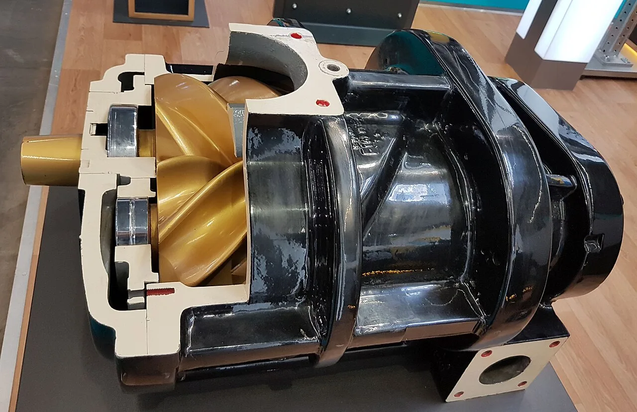
An axial compressor is a dynamic, multi-stage machine in which gas flows essentially parallel to the shaft through successive rows of moving rotor blades and stationary stator vanes, each row doing a small share of the total pressure rise, so that very large volume flows are compressed at efficiencies and footprints no other architecture reaches. A single casing may carry from a handful to twenty or more stages, adjustable stator vanes in many designs reshape the machine's operating envelope, and the design practice for process service is anchored in the API 617 framework for centrifugal and axial compressors. Baker Hughes's centrifugal and axial compressor lines are a representative industrial catalog, and this page treats the complete machine, casing, rotor, blading, seals, and train, as the purchasing object.
This page is written for the engineer specifying an axial compressor for an air separation plant, a blast furnace or FCC air duty, an LNG or large refrigeration service, a mine ventilation and process air installation, or the front of a process train whose flows are beyond a centrifugal machine's intake. It works through what the machine is and what is being bought, how the blade rows and the matching do the work, which designs fit which duties, the parameters that appear on vendor data sheets, and the selection factors and RFQ language that decide whether the compressor delivers its duty for an aeromechanical and train budget that stays predictable.
The decision concentrates in five places: the gas and its inlet conditions, composition, flow, pressure, and temperature, the total pressure ratio and the stage count that delivers it, the operating envelope, surge margin and turndown the process demands, and the hardware that shapes it, adjustable stators, intercooling, or axial-centrifugal combination, and the train, driver, gear, and control, that must start, stop, and protect the machine through every operating case. Get those right and the casing, the blading, and the API scope follow with little freedom.
Chapter 1 / 06
What an Axial Compressor Is and What Is Being Decided
The machine this page describes is a horizontally split or barrel casing, by pressure class, containing a rotor on journal and thrust bearings with rows of aerodynamically profiled blades, and the stator rows of vanes that carry the reaction between them. Gas enters axially at the first stage, each rotor row adds energy as it accelerates and turns the flow, each stator row converts that velocity to pressure and redirects the flow to the next stage, and the annulus tapers along the machine as density rises so the blade heights shorten from stage to stage, the visible signature of an axial machine opened for inspection. Adjustable stator vanes, where fitted, rotate on trunnions to restagger the early stages; seals at the shaft ends, labyrinth or dry gas by process class, and a balancing drum against the thrust the pressure field generates complete the internal machine.
What is being decided when an axial compressor is purchased is a flow and pressure ratio at stated inlet conditions with an efficiency and an operating envelope the process can live inside, backed by an aeromechanical and train statement. The buyer is purchasing a stated volume flow at a stated discharge pressure from stated inlet conditions, at a polytropic or isentropic efficiency the vendor guarantees, with surge and choke boundaries and the turndown the process needs, in a machine whose rotordynamics, blade natural frequencies, and driver system are engineered as one train under the API 617 practice framework. Everything on the vendor data sheet, stage count, pressure ratio per stage, speed, power, exists to support those guarantees, and the honest vendor shows the aerodynamic matching and the mechanical analysis, not only the performance map.
The axial compressor sits in the compression family with defined neighbors. Against the centrifugal compressor, the radial machine whose impeller throws gas outward, the axial delivers several times the volume flow per casing at lower per-stage ratio, and the two share the API 617 framework and many duties; large trains use them in series, axial first for volume, centrifugal or several after for ratio. Against the screw compressor and the reciprocating compressor, the positive displacement machines, the axial trades pressure ratio and turndown per casing for overwhelming flow and steady, pulse-free running. Against the gas turbine, the axial machine is the core component the turbine carries, but this page's machine is the industrial process and air compressor, not the engine's internal stage set, and the distinction matters to the buyer's specification.
Different buyers buy the same machine for different gases. An air separation plant buys large air compressors, axial intake sections, often with centrifugal rear stages on the biggest machines, feeding cryogenic separation trains. A steel plant buys blast furnace blowers, the classic single-purpose axial service, and wind tunnel and mine service compressors share the duty class. An LNG plant and large refrigeration users buy process axial machines, including mixed refrigerant services, often with a turboexpander elsewhere in the cycle recovering energy. A refinery buys axial machines for FCC air and wet gas duties, the plant air and instrument air systems served by smaller machines whose discharge passes an aftercooler and an air dryer. The specification language differs, but the stage-matching physics is shared.
The economics deserve their own paragraph because the axial machine is bought for scale. Its flow per unit of installed power and floor area is the best in the compression family, and at the top of the flow range it has no competitor at all, centrifugal casings would multiply into impracticality and positive displacement machines are not in the conversation; the plant air train of a major complex, the blower of an integrated steelworks, the refrigeration base load of an LNG line are axial duties because nothing else reaches the flow. Against that stand the machine's demands: an aeromechanical discipline in design and operation, surge protection as a life safety system for the blading, and maintenance that handles blades, not valves. The buyer pays for scale and efficiency and accepts an engineered machine.
A short tour of named duties makes the machine concrete. At an air separation complex, an axial intake section delivers hundreds of thousands of normal cubic meters per hour to a cryogenic cold box, intercoolers between stage groups, and a knockout drum guarding the train against condensate. At a steelworks, a blast furnace blower runs continuously at two to five bar discharge against a furnace schedule, its adjustable stators trimming the operating point through the campaign. At an LNG site, a process axial machine in the mixed refrigerant service runs in a train with driver and gear, its envelope protecting against the startup and turndown cases the liquefaction technology defines. Each duty names the same knobs, flow, ratio, matching, and surge margin, with sizes that scale while the stage physics barely changes.
Chapter 2 / 06
How the Blade Rows and Stage Matching Do the Work
Each stage is a small dynamic compressor. The rotor row does work on the gas, its blade profiles acting as airfoils that turn and accelerate the flow, and the stator row that follows decelerates that flow in controlled diffusion, converting kinetic energy to pressure, and presents the gas to the next rotor at the angle it needs; the degree of reaction, how the pressure rise divides between rotor and stator, is a design choice with fatigue and efficiency consequences, and the per-stage pressure ratio is kept low, a fraction of what a centrifugal stage achieves, because the diffusion in a blade row can only go so far before the boundary layers separate and the stage stalls. Many small stages, well matched, make the machine.
The annulus taper is density made visible. As the gas compresses stage by stage, its specific volume falls, and to keep axial velocity in its aerodynamic window the blade height must fall with it, so the compressor's flow path is a cone, tall blades at intake, short blades at discharge; the last stages of a high ratio machine are rings of small blades whose behavior is sensitive to everything upstream. Intercooling interrupts the taper in many process machines, extracting heat between stage groups so the later stages work on denser, cooler gas and the train's efficiency rises; intercoolers are shell-and-tube or compact cores, the printed circuit heat exchanger family serving high pressure intercool duty, and their pressure drops are part of the train's accounting.
Surge is the boundary every operation lives inside. Below a minimum flow at a given speed the early stages stall, the pressure field collapses and reverses, and the machine surges, flow slamming backward and forward at the system's Helmoltz frequency, loading blades and shafts beyond anything continuous duty allows; repeated surge destroys blading, and the antisurge system, flow measurement, a fast recycle or blow-off valve, and the control logic that opens it before the boundary, is a safety system, not a process nicety. Choke, the high-flow boundary where the stages run out of diffusion, sets the other edge of the map. The operating envelope between them, widened by adjustable stators, by speed variation, and by the recycle line, is what the process actually buys.
Adjustable stator vanes reshape the machine itself. By rotating the inlet stage vanes, and in some machines several rows, the operator changes the flow angles the early stages see, moving the surge line, shifting the efficiency island, and extending turndown far below what speed control alone would allow, blast furnace blowers and air separation machines run this way, their inlet vanes trimming the envelope continuously. Variable geometry adds hardware, trunnions, actuators, linkages, and a control loop that must be honest, and it buys the operating range that process schedules demand. Machines without it rely on speed and recycle, and their envelope is narrower by design.
Rotordynamics and aeromechanics are the machine's mechanical spine. The rotor is a stacked assembly, disks or drum, blades, and spacer hardware, whose critical speeds must sit clear of the operating range through the whole train, casing, coupling, driver, and gear included; blade natural frequencies must clear the running stimuli with margins the practice documents specify, and stall flutter, the aerodynamic excitation of blades at off-design, is the failure mode the matching and the vfd-speed or stator-vane schedules exist to avoid. Thrust from the pressure field is balanced by drum areas and carried by a thrust bearing, and the machine's protection, vibration probes, thrust position, and temperature instrumentation wired to trips, is engineered as part of the train under the API framework's machinery protection practice.
Degradation has an honest aeromechanical list. Blade fouling, from process or airborne deposits, thins the aerodynamic profiles' effectiveness, and efficiency and margin drift down until an offline wash or a service recovers them; online wash systems exist for exactly this. Erosion, in dusty service despite inlet filtration, changes blade contours permanently. Tip clearance growth, from casing wear or rubs, is the quiet efficiency thief. Blade cracking from flutter or resonance is the catastrophic mode the design margins and the protection system guard. None of these are exotic, and all of them are trended by the instrumentation the machine ships with, which is why the instrument scope belongs in the RFQ rather than the aftermarket.
Chapter 3 / 06
Machine Types, Train Architectures, and Boundaries
Straight axial machines, all axial stages in one casing, serve the high flow, moderate ratio duties: blast furnace air, mine and wind tunnel service, large plant air at low ratio. As the required ratio rises the axial stage count grows uneconomic, and the design world moves to combined machines, integral axial-centrifugal compressors whose axial section takes the volume and one or more centrifugal stages take the final ratio, a common air separation architecture, or to separate machines in series, axial then centrifugal casings on a train. The combined machine saves casing count and complexity; the series train keeps each machine in its best regime and adds the train engineering of matching them.
Casing construction follows pressure class. Horizontally split casings open for inspection and blade service without breaking the gas path, standard at the lower discharge pressures; barrel or vertically split constructions serve the higher pressure and the sour or hazardous classes, the inner bundle withdrawing axially. The gas path materials follow the gas, stainless and higher alloys for corrosive process service, standard steels for air; seals run labyrinth for inert service and dry gas seals for hydrocarbon and toxic duty, their supply and barrier systems part of the train scope. Stage groups and intercooling arrangements name the variants within a casing, and the thermal and nozzle loads land on the piping design as with any API machine.
Driver architectures name the trains. Steam turbine drive suits plants with steam, the turbine and compressor sharing the train engineering, and the steam turbine's own page covers that machine; electric drive runs synchronous motors at the fixed speeds the process allows, started through vfd, fluid coupling, or starter schemes the train study chooses, and the variable speed options serve processes with broad schedules; gas turbine drive appears in remote and liquefaction service, the machine's own power turbine driving the compressor train, and the heat recovery steam generator of such a plant closes the steam balance around the other machines. Gears, where speed matching demands them, add their own practice to the train.
The duty boundaries against the neighbors deserve precision. Below the axial machine's flow range, the centrifugal compressor takes over at higher ratio per casing, and its page covers that machine's volutes and impellers; below the centrifugal's flow range, and for high ratio, intermittent, or modular duties, the screw compressor and the reciprocating compressor serve. For low pressure air service the centrifugal fan and its page's machine move gas at blower ratios without the axial's compression. In the plant, the axial machine's discharge hands to the cooling and drying hardware, the aftercooler, an air cooled heat exchanger or water-cooled shell, then a knockout drum, then the air dryer for instrument air service, and the plant's utilities around it, the cooling tower and its water, the deaerator and feedwater heater of the steam cycle if the plant has one, are neighbors by service rather than by machine family.
Adjacent process equipment completes the picture. Inlet filtration, weather hoods, stages of barrier and fine filter, protects the blading and sets the erosion budget; antisurge and recycle systems, valve, cooler, and controls, protect the machine; and the process side receives the flow, the cold box of an air separation plant, the furnace of a steelworks, the reactor of an FCC unit, the liquefaction train of an LNG line with its lng vaporizer and refrigeration hardware at the product end, or the steam methane reformer of a hydrogen complex consuming plant air. Inlet air chilling with an absorption chiller even boosts the axial machine's mass flow in hot climates, a retrofit that pays where summer derate hurts. The RFQ names the machine's duty; the train names everything else.
Chapter 4 / 06
Key Specification Parameters
The vendor data sheet for an axial compressor centers on flow, ratio, speed, and power, and each number carries a train consequence. The table below lists the parameters that recur across manufacturers' quotations, with typical ranges for process and air classes; values for a specific project come from the process design and the vendor's aerodynamic matching, and the ranges here are orientation, not a substitute for a designed selection.
Parameter
Typical catalog range
What it decides
Inlet volume flow
50,000 to over 1,000,000 m3/h
Whether the duty is axial at all
Pressure ratio, straight axial
2 to 8 by stage count
Stage count; intercooling; combined architecture
Stage count
5 to 20 plus
Casing length; matching complexity
Polytropic efficiency
85 to 92 percent by class
Driver power; energy per unit flow
Adjustable stator rows
none to first 3 to 5 rows
Turndown and surge margin shaping
Speed
3,000 to 12,000 rpm typical
Driver and gear architecture
Power
5 to 80 MW by duty
Driver class; electrical or steam balance
Surge margin guaranteed
stated at rated point
Operating envelope; antisurge setpoints
Three of these numbers deserve the buyer's suspicion when they arrive without a basis. Efficiency quoted at the design point without the map's behavior at the process's real operating points flatters a machine that will live elsewhere. Surge margin quoted without stating the reference flow and the tolerance of its measurement is a number, not a protection. Turndown quoted without naming the mechanism, speed, stators, recycle, or their combination, hides the control scope the plant must buy to realize it. An RFQ that fixes the operating cases, not just the design point, separates engineered offers from assembled ones.
Materials and construction follow the gas and the practice. Blading runs stainless families and higher alloys by temperature and corrosion class, titanium where its mass helps the rotordynamics; casings and diaphragms run cast and fabricated steel by pressure class; seals run labyrinth or dry gas by process hazard with their systems in the train scope. The API 617 practice context governs the machine's specification discipline, data sheets, testing, rotordynamic analysis, and the vendor's documentation, in the edition current at contract, and the buyer's specification invokes it rather than paraphrasing it.
Chapter 5 / 06
Selection Decision Factors and RFQ Language
Selection starts with the process duty, not the catalog. The gas, its composition and inlet conditions, the flow and pressure ratio, and the operating cases, rated, normal, minimum, and upset, define the machine; the aerodynamic matching and the map, not the nameplate, decide whether the process lives inside the envelope. The train question follows, driver, gear, and train dynamics as one system, and the control question, antisurge and performance control integrated with the train's, is bought with the machine or fought without it. A buyer who specifies a design point and nothing else has specified a test stand, not a machine.
The architecture choice follows ratio and schedule. Straight axial serves the low ratio, high flow, steady duties; combined axial-centrifugal machines serve air separation and moderate ratio service elegantly; series trains with separate machines serve when the ratio or the process staging demands them. Adjustable stators buy turndown where the process swings, blast furnace and variable air duty; fixed machines with recycle serve steadier processes. The economic comparison, one casing versus two, motor start schemes, intercool count, belongs to the study with the vendor's real maps on the table.
The table below organizes the decision into the factors that recur across projects, with the questions the buyer should be able to answer before the RFQ goes out. Each row is a place where an incomplete answer turns into an underspecified train and an availability argument later.
Discharge pressure plus all operating and upset cases
Envelope unknown; antisurge mis-set
Turndown need
Minimum stable flow and its mechanism
Fixed machine bought for a swinging duty
Train architecture
Driver, gear, train dynamics scope
Critical speed or start scheme surprises
Practice framework
API 617 edition current at contract, testing scope
Documentation and test gaps
Protection scope
Antisurge system, instrumentation, trips
Safety system improvised after delivery
Site and climate
Inlet conditions, filtration class, hot climate derate
Erosion and summer capacity losses
RFQ language for an axial compressor should name the duty and the basis of guarantee. A workable specification states: gas composition with inlet pressure and temperature at each case; volume or mass flow and discharge pressure for rated, normal, minimum, and upset cases; required efficiency basis and the map acceptance; surge margin requirement and antisurge system scope; architecture intent, straight, combined, or series, with intercooling; speed and driver intent with the train rotordynamic scope; the API 617 practice framework in the edition current at contract with the test regime, aerodynamic and mechanical, witnessed points included; materials by gas class; and instrumentation and protection scope wired to trips. Naming the train neighbors, the driver, the gear, the aftercooler or intercooler hardware and its class, the knockout drum, and the inlet filtration, lets the vendors bid the machine's whole duty rather than its casing alone.
Chapter 6 / 06
Installation, Standards, Failure Modes, and Maintenance
Installation is a train campaign. Foundations carry the machine, gear, and driver as an aligned system; the machine and its train partners are aligned to the tolerances the practice documents specify, soft foot and bracket considerations included; the piping lands within the nozzle loads the vendor analyzed, because casing distortion is an aerodynamic and rotordynamic event, not just a mechanical one. Commissioning proves the protection system before the process, antisurge valve stroked fast, trips proven, vibration baseline recorded, and the first runs map the machine against the vendor's predicted map, with surge testing to the extent the contract dared to specify. The vendor's engineers stay through the performance test, and an RFQ should price that presence explicitly.
Standards for these machines are the API framework's home ground. The API 617 practice for axial and centrifugal compressors governs the machine's specification discipline, data sheets, analysis scope, rotordynamics, and testing, in the edition current at contract, and the train's other members carry their own practice documents, drivers, gears, and lubrication systems under their standards; instrumentation follows the machinery protection practice the framework references. The buyer's specification invokes the framework and its editions rather than paraphrasing them, and any edition reference in project documents should be checked against the current issue at purchase rather than copied from an old specification.
The recurring failure modes are aeromechanical and mostly trended first. Blade fouling and erosion degrade performance and margin gradually, and the trend of efficiency, pressure ratio at conditions, and vibration tells the story seasons before service; online and offline washing recover what fouling takes. Tip clearance growth, rubs, and casing distortion are the quiet efficiency thieves and the vibration signatures catch them. Blade cracking from flutter or resonance is the catastrophic mode, guarded by design margins, by the operating schedules that avoid the excitation regions, and by the protection trips that answer when margins are violated. Thrust bearing wear, seal degradation, and the antisurge system's own reliability, a valve that must stroke in milliseconds after years of sitting, complete the honest list.
Maintenance planning is condition driven with long internals. The table below lists the actions with the typical cadence a plant will schedule, assembled from common practice; actual intervals follow the gas cleanliness, the duty's severity, and the trend record, and should be set from the machine's own data.
Item
Typical action
Typical cadence
Performance trend
Compute ratio and efficiency at conditions
Continuous to weekly
Vibration and thrust
Trend spectra and positions against baseline
Continuous
Online wash
Solvent or water wash per fouling trend
On trend, weekly to monthly
Antisurge system
Proof-test valve stroke and control response
Quarterly to semiannual
Inlet filtration
Change stages, verify dP and integrity
Per differential
Internal inspection
Open, blade and clearance inspection
3 to 6 years by trend
Seals and bearings
Service per practice and trend
At overhauls
Long term care is a trend record and an overhaul economy. The machine that reaches decades of service does so on the strength of its instrumentation's honesty and the plant's discipline in answering it, washing before fouling sets, opening before margins vanish; overhauls, blade replacement by condition, clearance restoration, seal renewal, are scheduled from the record rather than the calendar, and retrofit options, restaggered blading, upgraded seals, and control modernization, extend legacy trains to modern efficiency. The plant that treats the axial machine as the instrument it is, mapped and trended and protected, runs the flow nothing else can deliver for the life of the complex it serves.
FAQ
What is the difference between an axial and a centrifugal compressor?
An axial compressor moves gas parallel to the shaft through successive rotor and stator blade rows, each stage adding a small pressure rise, and it excels at very large volume flows with high efficiency. A centrifugal compressor throws gas radially from impellers, achieving much higher pressure ratio per stage at lower flows. The two share the API 617 practice framework and often work in series or in combined machines, axial for volume at the front, centrifugal for ratio at the back.
What are adjustable stator vanes and why do they matter?
Adjustable stator vanes are inlet stage stationary rows that rotate on trunnions to change their angle to the incoming flow. Restaggering them moves the surge line, shifts the efficiency island, and widens the machine's operating range far beyond what speed control alone allows, which is why blast furnace blowers and air separation compressors run them. They add actuators, linkages, and a control loop, and they buy the turndown that swinging processes demand.
What is surge in an axial compressor and how is it prevented?
Surge is the flow instability below minimum stable flow where stage stall collapses the pressure field and flow reverses cyclically at the system's frequency, loading blades and shafts violently enough to destroy blading in repeated events. Prevention is the antisurge system: continuous flow measurement, a fast recycle or blow-off valve, and control logic that opens it before the boundary, plus the operating schedule, speed, stators, and recycle, that keeps every process case inside the guaranteed envelope. The antisurge system is a machine safety system and is specified as one.
What is an axial-centrifugal combined compressor?
It is a single machine whose first stages are axial and whose last one or more stages are centrifugal, the axial section taking the large inlet volume flow and the centrifugal stages delivering the final pressure ratio efficiently. The architecture is common in large air separation and process air service where the duty is beyond a straight axial machine's ratio but a separate centrifugal casing would waste train complexity. It trades casing count for internal complexity and is offered within the same API 617 practice framework.
What duties are axial compressors typically bought for?
The highest volume flows in industry: main air compressors for air separation plants, blast furnace blowers for steelworks, FCC air in refineries, large plant and instrument air systems, mine ventilation and wind tunnel service, and process refrigerant duty including LNG service. The common thread is flow beyond the centrifugal machine's comfortable intake at moderate pressure ratio, with steady duty and an engineered train. Below those flows, centrifugal and positive displacement machines take over.
How is an axial compressor started and driven?
By large synchronous motors through variable frequency, fluid coupling, or starter schemes, by steam turbines where the plant's steam balance favors them, or by gas turbines in remote and liquefaction service. Starting matters because the machine must accelerate through regions where its aerodynamics are awkward, and the scheme, vfd, starter motor, or blow-off, is a train decision made with the vendor. Gears match speeds where driver and machine differ, and the whole assembly is analyzed as one train for critical speeds.
What should an axial compressor RFQ include?
State the gas composition and inlet conditions at every operating case, flow and discharge pressure for rated, normal, minimum, and upset duty, required efficiency basis and map acceptance, surge margin and antisurge scope, architecture intent with intercooling, speed and driver architecture with train rotordynamic scope, the API 617 framework in the edition current at contract with the test regime, materials by gas class, and instrumentation and protection wired to trips. Naming the train hardware, driver, gear, coolers, knockout drum, and inlet filtration, lets vendors bid the machine's whole duty.