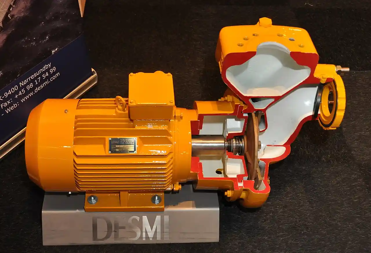
A split-case pump is a between-bearings centrifugal pump whose casing parts on a plane through the shaft centerline, so the rotating assembly lifts out for service without disturbing the suction and discharge piping. Almost every build carries a double-suction impeller, with liquid entering both sides of the impeller simultaneously, which halves the flow per side, drops the required NPSH, and balances axial hydraulic thrust by symmetry. The architecture serves high flow, moderate head, clean liquid duty: municipal supply and transmission, desalination and brine transfer, district cooling, industrial cooling water, and pipeline charge, across flows from roughly 100 to 40,000 m3/h and heads up to about 400 m in two-stage builds.
Procurement engineers meet this pump where a single machine must be trusted with a city district's water or a plant's cooling loop, and where maintenance access decides uptime. The decision this page settles is narrow and practical: when the axially split between-bearings build earns its premium over an end-suction or vertical turbine alternative, what double suction buys in NPSH margin and thrust life, how single-stage and two-stage builds divide the duty space, and what the casing split, seal, bearing, and test lines of an RFQ must say so the quotation that comes back is a machine, not a brochure. Every chapter feeds that line set, because a split-case pump bought on flow and head alone is a foundation and alignment problem deferred.
This page treats the split-case pump as a purchasing object: what the axial split and the double-suction impeller change in measurable numbers, how single-stage and two-stage builds divide the duty map, what API 610 BB1 and HI test language pins down, and how casing material, seal, and driver choices combine into a defensible RFQ. It is written for engineers who issue purchase specifications, not for readers who want a catalog summary.
Chapter 1 / 06
What a Split-Case Pump Is and What Is Being Decided
The casing split is the defining feature and the maintenance promise. In an end-suction pump, the impeller hangs off the end of the shaft with bearings on one side only, and major service means breaking the piping or removing the motor. In a split-case pump, the shaft runs between two bearing housings and the casing halves separate on the horizontal centerline, so the upper half lifts and the rotor, impeller, shaft, bearings, and wear rings, comes out as an assembly with the suction and discharge flanges untouched. That promise is why municipal and industrial plants tolerate the longer, heavier, costlier machine: a rotor swap or a wear-ring renewal is a day of planned work instead of a week of rigging.
The double-suction impeller is the hydraulic signature. Liquid enters the impeller from both sides through a split casing passageway, so each eye sees half the flow. Required NPSH falls accordingly, typically by 30 to 50 percent against a single-suction impeller of the same duty, which is what lets these pumps run at 1450 or 2950 rpm on open sump suction where a single-suction machine would cavitate. Axial hydraulic thrust balances by symmetry, the two sides push against each other, so the thrust bearing carries only residual and misalignment loads instead of the full unbalanced load of an overhung impeller, and bearing life stretches with it. The result is a pump that runs flat-out for decades on clean water duty, which is precisely the service it owns.
What is being decided in this purchase is whether the duty earns the architecture. Split-case pumps dominate where all three of the following hold: flows above roughly 500 m3/h where end-suction frames run out of bearing credibility; clean, non-abrasive liquids, because the double-suction passageway and the tight wear-ring annuli punish solids; and a maintenance culture that values in-place rotor service. Where any of the three fails, a different machine wins: end-suction pumps below the flow band, vertical turbine pumps on wet wells and cooling intakes, multistage ring-section or barrel pumps at high head, and slurry pumps when solids dominate. The selection chapter runs that comparison honestly, including the vertical split-case variant that trades the horizontal parting plane for a smaller footprint.
The family this page covers is the industrial and municipal water workhorse, and its boundaries matter for specification. A fire pump built in split-case configuration for NFPA 20 duty is a listed machine with its own certification logic, and the fire pump leaf carries that discussion; here it is enough that the same hydraulics serve a different code world. The boiler feed pump leaf covers the multistage ring-section and barrel architectures that high discharge pressure demands; two-stage split-case builds reach only partway into that territory. The vertical turbine pump owns the wet-pit intake; the submersible pump owns the wet well itself; and the axial-flow pump owns very high flow at very low head. The split-case pump takes the broad middle: high flow, moderate head, dry-pit or can installation, clean liquid.
Standards organize the datasheet. ISO 5199 and ANSI/HI 14.6 frame general industrial and test acceptance; API 610 is the petroleum and heavy-duty rulebook, in which the axially split between-bearings single- and two-stage build is the BB1 configuration and the axially split multistage build is BB3; NSF/ANSI 61 and equivalent drinking-water listings govern potable service materials; ISO 9906 grade columns convert test readings into acceptance bands. A datasheet that quotes none of these is a price tag, and the chapters below attach each of them to the row where it bites.
Chapter 2 / 06
How the Double-Suction Impeller Shapes Performance
Mechanically the pump is a textbook centrifugal machine with one decisive change at the impeller eye. The casing forms a passageway that feeds liquid to both sides of a double-inlet impeller; the impeller discharges into a single volute or a double volute; the shaft pierces the casing at both ends through bearings, seals, and coupling. Because each eye passes half the total flow, the inlet velocity stays low, the NPSH required curve drops, and the pump tolerates suction conditions, long approach piping, modest submergence, warm water, that would push a single-suction machine into cavitation. On municipal raw water at 25 deg C with a sane sump, NPSH margins of 1.5 to 3 m above required are routine rather than engineering victories.
Thrust balance is the second structural dividend. An overhung impeller sees full hydraulic axial thrust, sometimes tonnes on large machines, and its thrust bearing sizes accordingly. The double-suction impeller cancels the two sides' thrust against each other, so the residual thrust carried by the bearing is a fraction, often under 10 percent, of the equivalent single-suction load. In practice this shows up as L10 bearing life well beyond the API 610 minimum of 25,000 hours continuous, with 100,000-hour lives common on clean water duty. The symmetry also centers the rotor hydraulically, which keeps wear-ring clearances even and slows the internal recirculation loss that aging pumps suffer.
The performance envelope is worth quoting in ranges a specifier can check. Single-stage double-suction pumps run flows of roughly 100 to 40,000 m3/h, heads of 10 to 150 m, and efficiencies of 80 to 88 percent at BEP for the larger sizes, among the best hydraulic efficiencies in the pump world, because the clean water duty and low inlet losses let designers optimize the impeller without compromise. Two-stage builds stack two impellers in series inside the same axially split casing and reach 400 m of head; beyond that the duty belongs to multistage ring-section or barrel pumps. Specific speed placement keeps the impellers in the radially bladed, non-cavitating band, and the flat-to-moderate head-capacity curves suit parallel station operation where two to six pumps share a header.
Where the pump sits in the system decides its operating health. Split-case hydraulics want to run between roughly 70 and 120 percent of BEP flow; sustained operation far below that band recirculates at the impeller eye, churns the inlet, and wears the double-suction passageway lips; sustained operation far above runs the NPSH curve up a wall. Suction layout matters as much: the ideal approach is a straight run of 5 to 10 pipe diameters into each side of a double-suction inlet, and the classic field error is an elbow immediately upstream, turned in the plane that biases flow to one side, which starves one impeller eye, destroys the thrust symmetry, and doubles shaft deflection. The suction specific speed number, typically 8,000 to 11,000 US units for these designs, is the early check that a quoted hydraulic is not an inlet-compromised promise.
Driver and control complete the machine. Most municipal and industrial split-case pumps ride on a direct-coupled induction motor, the ac motor leaf covers the machine itself, at 2, 4, or 6 pole speeds matched to the hydraulic; variable speed via a vfd suits transmission systems with wide demand swings and often lets one pump cover a duty two fixed-speed machines shared. High-specific-speed builds at high flow behave like square-law loads, so a small speed trim moves flow a lot, and overspeed checks belong in the purchase review. On engines, fire and remote duty aside, the between-bearings rotor tolerates torsional loads better than an overhung design, but the alignment and coupling chapters of the installation section apply to both drivers.
Cavitation and air are the two field killers. Cavitation announces itself as gravel noise and pitting at the impeller eye lips; its root causes are low sump level, blocked strainers, warm water, or the elbow-biased inlet. Entrained air, from vortexing sumps or leaking suction joints, is quieter and worse: 1 percent air by volume costs a few points of head, several points of efficiency, and enough bubble collapse to eat metal, and the double-suction passageway does not forgive it. Both failure families trace to suction engineering rather than the pump, which is why the RFQ block in chapter 5 demands the suction conditions in writing, sump submergence, approach geometry, liquid temperature, and not just flow and head.
Chapter 3 / 06
Types, Construction, and Duty Boundaries
Three construction axes divide the family: stages, split orientation, and suction arrangement. Single-stage builds with one double-suction impeller are the municipal and cooling-water standard, simple, robust, and efficient. Two-stage builds stack impellers in series for heads to roughly 400 m, feeding pipeline and boiler-feed-adjacent duty while keeping the axial split's service promise. The split orientation is normally horizontal, through the shaft centerline; vertically split casings, parting on a vertical plane, exist as footprint-saving variants for plants where floor length is scarce, and vertical-axis installations of horizontal-split machines appear in can-type or vertical turbine-adjacent stations. Each axis is a purchase line, not a footnote.
The axial versus radial split distinction carries code weight in API 610 language. An axially split casing parts parallel to the shaft; a radially split casing parts perpendicular to it, like a barrel. BB1 is the axially split between-bearings configuration covering one and two stages, the classic water workhorse admitted into petroleum duty when the service allows; BB3 is the axially split multistage configuration beyond the two-stage range; BB2 is the radially split equivalent. For clean hydrocarbon and utility services at moderate pressure, BB1 and BB3 split-case builds compete directly with overhung OH2 and radially split BB2 machines, and the split advantage, rotor service with piping intact, weighs heaviest where planned turnaround time is money. At high discharge pressure, casing flange bolt loading pushes design toward radial splits and barrel architecture, which is why the multistage pump leaf owns that territory.
Suction and discharge arrangement follows the station. Side-side and side-top nozzle placements dominate horizontal split-case builds, with the double-suction passageway feeding both impeller eyes from one suction flange. Opposed nozzles suit inline stations; tangential discharges suit header rooms. The passageway itself is the reason split-case pumps prefer drawn, rectangular station layouts with generous approach runs: hydraulic symmetry assumes both eyes see the same flow, and the layout either honors that or spends the thrust balance to fix it. Wear rings at the impeller eyes and casings are the renewable clearance parts, typically 0.3 to 0.5 mm diametral clearance per 100 mm of diameter on new builds, and their growth marks the pump's aging curve.
Bearings, seals, and coupling define the service envelope. The between-bearings rotor runs on a pair of rolling-element bearings in most water builds, radial plus angular contact thrust, oil ring or grease lubricated, with hydrodynamic sleeve and tilting-pad bearings appearing above roughly 300 kW per stage or on high-speed duty where API 610 expects them. Sealing spans the full mechanical seal and packing spectrum: soft packing on benign, visible-duty water service; single and double mechanical seals, cartridge preference, on pressurized and treated water; and plan configurations, flush, quench, and barrier fluids, per API 682 where the service carries it. The coupling, usually a spacer elastomer or gear type, sets whether the driver moves for seal work without touching the pump, which is the same service-preservation logic as the casing split itself.
Materials follow the water. Cast iron casings and bronze-fitted trim, bronze impeller and rings on iron casing, is the century-old fresh-water default and still the economic answer for municipal duty. All-bronze or 316 stainless internals serve brackish and aggressive water; duplex stainless wetted parts answer seawater and high-chloride cooling circuits; and carbon steel casings with appropriate trim serve API-registered hydrocarbon utilities. Drinking-water service adds the listing layer: NSF/ANSI 61, or the local equivalent such as ACS or KTW, governs every wetted material and coating that touches potable water, and the certification belongs on the datasheet, not in a marketing footnote. Coatings, epoxy internal paint on iron, and carbon-steel externals, extend casing life in treated water but do not substitute for correct metallurgy in aggressive chemistry.
Duty boundaries, stated bluntly. This is not a solids machine: sand and silt above trace levels wear the double-suction passageway and rings out of tolerance quickly, and slurry pump or dedicated hard-metal architecture owns that duty. It is not a high-head machine beyond the two-stage ceiling: multistage ring and barrel builds take over. It is not a self-priming machine in its standard form: the passageway floods from a flooded suction or a priming aid, and where the sump cannot flood the suction, a self-priming pump or a vertical turbine owns the station. And it is not, in this leaf's scope, the listed fire pump of NFPA 20 skids, though the hydraulics are cousins; that purchase walks its own certification path. The table below consolidates the boundaries into a scan-friendly duty map.
Service
Construction to specify
Construction to avoid
Municipal potable supply, 500 to 10,000 m3/h
Single-stage BB1, bronze-fitted or 316 trim, NSF 61 listing, cartridge seal
Unlisted coatings or bronze alloys on potable duty
Transmission pipeline, 150 to 400 m head
Two-stage BB3 axially split, duplex or 13Cr trim, vfd driver
Single-stage build pushed past its head ceiling
District cooling and condenser water
Single-stage double suction, 316 or duplex internals on treated loops
Bronze trim where chemical dosing attacks copper alloys
Desalination and brine transfer
Duplex stainless wetted, generous NPSH margin, mechanical seal with flush
Cast iron with bronze trim in high-chloride service
API utility hydrocarbon service
BB1 to API 610, mechanical seal per API 682 plan
Water-market builds without API material and test traceability
Raw water with seasonal silt
Hard-faced rings, wear allowance, upstream settling or straining
Standard clearances expecting sand-free water
Wet pit or sump intake
Vertical turbine pump instead
Dry-pit split-case starved by a bad sump retrofit
Chapter 4 / 06
Key Specification Parameters
The datasheet rows below decide whether a quoted pump matches the station. Each row is a purchase defining parameter; the paragraphs after the table explain what to demand and what a weak answer looks like.
Attribute
Typical range or options
What it decides
Capacity at rated point
100 to 40,000 m3/h; duty band 70 to 120 percent of BEP
Size, number of units, and where duty sits on the curve
Differential head
10 to 150 m single stage; to 400 m two stage
Stage count and whether the duty stays in this family at all
NPSH required and margin
NPSHr 2 to 15 m at rated; margin 1.5 to 3 m over NPSHa
Cavitation life and the suction engineering the station owes
Configuration
BB1 single stage, BB3 two stage; horizontal or vertical split
Service access, footprint, and code framing under API 610
Suction specific speed
8,000 to 11,000 US Nss at BEP
Inlet hydraulic quality and suction energy risk
Materials of wetted parts
Cast iron with bronze trim, all bronze, 316, duplex 2205
Water chemistry survival and listing eligibility
Sealing
Packing; single or double cartridge mechanical seal; API 682 plans
Leakage policy, maintenance class, and seal environment
Bearings and life
Rolling element standard; hydrodynamic above about 300 kW; L10 25,000 h minimum, 100,000 h typical
Continuous duty credibility and lube system scope
Driver and control
Direct-coupled ac motor, 2 to 6 pole; fixed speed or vfd
Energy cost over life and station turndown strategy
Test acceptance
ISO 9906 grade 1B or 2B; HI 14.6 witness points
The tolerance band the curve is bought against
Listings for potable duty
NSF/ANSI 61 or ACS, KTW equivalent, all wetted parts
Regulatory acceptance of materials on drinking water
Nozzle loads and flanges
PN10 to PN40 or CL125 to CL300; allowed loads per standard
Piping independence of the casing and alignment stability
The NPSH row deserves its own paragraph because it is where split-case purchases are quietly won. The double-suction impeller lowers NPSH required, but the benefit survives only if the station delivers symmetric, undisturbed approach flow and honest submergence. Demand the NPSH required curve, not a point, and demand it at the rated speed; check the margin at the worst credible operating condition, usually maximum flow on the lowest sump level and warmest water, not at BEP. A supplier who quotes a single NPSH number without the curve is asking the station to trust a spot sample of a hydraulic that may bend steeply just above duty flow.
The efficiency row pays for the whole specification effort. Large split-case pumps convert a single efficiency point into real money: on a 2,000 kW continuous-duty machine, one efficiency point is roughly 17,500 kWh per year, and the pump runs for twenty. Ask for the guaranteed efficiency at BEP and at rated point, the tolerance the test grade allows, and the wire-to-water honesty of any packaged quote. The stage-count decision belongs in the same conversation: a two-stage build running each stage at a comfortable specific speed often beats a single-stage machine pushed to its hydraulic edge on both efficiency and NPSH, and the RFQ that invites both proposals gets the better machine.
The construction rows convert maintenance philosophy into hardware. State who services the pump and how often: the axial split exists for in-place rotor work, and a station that cannot lift a casing half or stage a spare rotor buys the feature without the benefit. Wear-ring material and clearance, hard-facing where silt seasons the water, and a spare rotor assembly with rings and bearings are standard lines. The seal plan, flush, quench, or barrier, must match the liquid and the emissions policy. And the test scope, performance to the quoted grade, NPSH demonstration where margin is thin, and vibration acceptance at rated, is the buyer's only chance to see the truth before the foundation is poured.
Chapter 5 / 06
Selection Decision Factors and RFQ Language
The decision sequence runs as a checklist, and each step eliminates a class of quotations before price comparison begins.
Write the system curve honestly: static lift, friction at old-pipe roughness, and the flow band between night minimum and design maximum, because the pump is bought for the band, not the point.
Compute NPSHa at the worst credible combination, lowest sump, warmest water, maximum flow, and demand the NPSHr curve against it; a split-case pump that cavitates on paper cavitates worse in the station.
Choose stage count by specific speed comfort: single stage to roughly 150 m, two stages to 400 m, and hand the duty to the multistage pump family beyond.
Fix materials from the water analysis, including the seasons, and add the drinking-water listing where potable.
Decide the sealing policy, packing, single, or double cartridge with its plan, against the leakage and emissions standard the site enforces.
Fix the driver and control philosophy, fixed speed with throttling stations or vfd on transmission duty, and check motor starting method against the supply.
State the maintenance contract: in-place rotor removal clearance, casing half lifting, and the spare rotor strategy, so the axial split pays for itself.
Fix the verification evidence: performance and NPSH test to the quoted ISO 9906 or HI 14.6 grade, vibration acceptance, material certificates, and the certified curve pack for the station file.
Against neighboring pump types, the comparison a specifier actually runs is the following, and it belongs here rather than in the page title. Against the end-suction overhung pump, the split-case build wins above roughly 500 m3/h on bearing credibility, NPSH, and rotor service, and loses on footprint and first cost below it. Against the vertical turbine pump, the split-case wins where the water arrives by pipe rather than from a wet pit, and loses where the intake is the sump itself. Against the multistage pump family, ring-section and barrel builds own high head; the two-stage split-case takes the band up to about 400 m and no further. Against dedicated duty pumps, the fire pump owns NFPA 20 listing, the self-priming pump owns unflooded suctions, the slurry pump owns solids, and the submersible pump owns the wet well. Choose the machine the station's physics demands, not the one a supplier has on promotion.
The application map below turns that comparison into a table the project file can carry into bid evaluation.
Application
Construction to specify
Check before order
City transmission main
Two-stage BB1, duplex trim, vfd, spare rotor in store
NPSH margin at low reservoir; parallel operation curve overlap
Single stage, bronze or 316 per treatment, packing option
Sump approach symmetry; strainer upstream of rings
High-rise booster zone
Vertical split variant or multistage alternative
Footprint versus rotor-access trade made explicitly
The RFQ block should be written once and reused. A complete block reads: quantity and configuration, single or two stage, horizontal or vertical split; rated flow, head, and the operating band with system curve attached; liquid, temperature range, solids expectation, and full water analysis; NPSHa at worst case with sump or suction arrangement drawn; materials for casing, impeller, rings, and shaft; wear-ring clearances and hard-facing; seal type and plan; bearing type, lubrication, and L10 statement; driver rating, voltage, and control method; flange ratings and allowable nozzle loads; test grade with witness points for performance, NPSH, and vibration; drinking-water listing if potable; spare parts, rotor assembly, rings, and gaskets; and the certified documentation pack, curves, material certificates, and test reports, with the retention the station file requires. A quotation returned without the NPSH curve or the test-grade statement is incomplete at any price.
Chapter 6 / 06
Installation, Standards, Failure Modes, and Maintenance
Installation decides whether the axial split ever pays its promise. Foundations carry the pump and driver on a common grouted base with anchor bolts aligned to sub-millimeter tolerance before grouting; coupling alignment, laser preferred, runs to the tolerance the coupling maker states, typically 0.05 to 0.10 mm at the rim for elastomer spacers at these speeds. Suction piping honors the double-suction symmetry: a straight run of 5 to 10 diameters into the inlet, elbows avoided in the plane that biases flow, and a flat-bottom entry when the source is an open channel. The suction strainer, a start-up y strainer or permanent basket depending on the water, protects new wear rings from welding bead and scale during commissioning, when clearances are tightest and water is dirtiest. Discharge piping carries a check valve close to the pump and an isolating gate or butterfly valve beyond it, and the header design supports the nozzle loads the datasheet allows without leaning on the casing.
Commissioning protects the hydraulic investment. Flush the suction before first start; flood and vent the casing and the seal region completely, because a dry start on a mechanical seal is a scrapped seal in seconds; bump the rotation against the uncoupled motor if there is any doubt; then run the machine against a cracked discharge valve toward duty and record suction and discharge pressures, motor amps, flow where metered, and vibration at bearing houses. The baseline vibration signature, in mm per second RMS at the bearing housings, becomes the condition-monitoring reference for the station's life, and a pressure transmitter on discharge plus a flow meter where the process justifies one turn the pump curve into live operating data.
The standards frame is short and enforceable. API 610 defines BB1 and BB3 configurations, material classes, and test expectations for petroleum-duty purchases; ANSI/HI 14.6 with ISO 9906 grades fixes how performance, NPSH, and vibration tests are read, grade 1B or 2B acceptance being customary for water duty; NSF/ANSI 61 and its regional equivalents govern potable-water materials; API 682 governs seal plans where the service carries them. Citing the standards by name in the RFQ transfers the burden of proof to the supplier, which is where it belongs.
Failure modes follow a short, predictable list. Cavitation from sump or strainer problems: gravel noise, head droop, pitting at the eye lips; the fix is suction engineering, not a stronger pump. Wear-ring wear from silt seasons: internal leakage rises, efficiency decays a few points a year, and thrust symmetry erodes as clearances open; the fix is planned ring renewal on the axial split's schedule, which is precisely the service the casing split exists to give. Seal leakage: packing drips by design within limits, cartridge seals leak when the plan or the alignment fails, and face damage from dry starts is the classic commissioning casualty. Bearing distress: usually misalignment or imbalance in disguise, occasionally lube neglect; the between-bearings geometry makes replacement straightforward but does not forgive the causes. Shaft deflection from off-BEP operation: the impeller rubs rings on one side, the first symptom being a rising vibration line at running frequency. None of these modes surprises a station that kept its baseline signatures.
Maintenance economics follow the same plan the casing split was bought for. Quarterly: vibration readings against baseline, seal or packing condition, lube condition. Annually: alignment re-check, wear-ring clearance estimate from performance decay or internal clearance measurement at a planned outage, and ring renewal when internal leakage costs more efficiency than the outage costs downtime. At each major overhaul, typically 6 to 10 years on clean water, the rotor assembly comes out through the lifted casing half in a planned day, rings and bearings renew, and the machine returns with its birth curve restored; that hour budget, not the purchase price, is the number that justified the architecture. A station that records each pump's decay curve ends up with a purchasing file that gets smarter, because the next RFQ quotes the water it actually pumps, including the seasons.
FAQ
When should I choose a split-case pump instead of an end-suction pump?
Above roughly 500 m3/h of clean liquid, the between-bearings double-suction build earns its premium: NPSH required drops 30 to 50 percent, axial thrust balances by symmetry, bearing life stretches well past API minimums, and the rotor services through the lifted casing half without breaking piping. Below that band, end-suction machines are cheaper, smaller, and entirely adequate. The honest dividing line is the duty point where an overhung machine's thrust bearing and suction margin stop being comfortable.
What does double suction actually buy in NPSH terms?
Each impeller eye passes half the total flow, so inlet velocity stays low and the NPSH required curve drops 30 to 50 percent against an equivalent single-suction design. On a flooded municipal suction that converts into routine margins of 1.5 to 3 m, and it lets 2-pole builds run where single-suction designs would cavitate. The benefit is only real if the approach piping feeds both eyes symmetrically, so the suction layout belongs in the purchase specification, not the installer's discretion.
What do API 610 BB1 and BB3 mean?
They are the between-bearings configuration codes in API 610: BB1 is the axially split build covering one and two stages, the classic water workhorse with heads to about 400 m, and BB3 is the axially split multistage build beyond that range. The axial split is the service promise, rotor removal with piping in place, and the code adds the material classes, bearing life minimums, and test framing that hydrocarbon sites require. Water-market builds without API traceability should not be quoted as equivalents.
Can a split-case pump serve as a fire pump?
The hydraulics are cousins, but a listed fire pump is its own purchase. NFPA 20 duty requires a pump listed and certified for fire service, with its own test, churn, and acceptance logic, and the fire pump leaf carries that rulebook. What is true here is that split-case configurations are one of the listed fire pump architectures, so a municipal station can standardize spare parts across listed and unlisted machines deliberately, as a parts strategy, not as a substitution.
What materials do I need for drinking water or brackish duty?
For potable service, every wetted material and coating carries NSF/ANSI 61 or the regional equivalent such as ACS or KTW, and the listing is a datasheet line, not a brochure claim. For brackish and cooling waters, 316 stainless internals answer moderate chlorides, duplex 2205 answers high chloride and brackish circuits, and bronze-fitted iron remains correct for clean fresh water. Match the trim to the water analysis including its worst season, and let the listing follow the alloys chosen.
How often do wear rings need renewal, and why does it matter?
On clean water, ring clearances grow slowly and overhauls land at 6 to 10 year intervals; in silty water the decay is faster and hard-faced rings buy time. It matters because ring wear is internal leakage: efficiency decays a few points, the curve softens, and as clearances open the thrust symmetry that the double-suction impeller provides degrades. Renewal is exactly the job the axial split exists for, a planned day with the piping untouched, so budget rings and bearings as consumables from day one.
Is packing still acceptable, or should I specify a mechanical seal?
Packing remains honest engineering on benign, visible-duty water service where a controlled drip is acceptable and the station values simple maintenance; it leaks by design within limits and wears the sleeve predictably. Cartridge mechanical seals suit treated, pressurized, and emissions-audited service, cost more up front, and demand correct plans, flush, quench, or barrier, and a flooded start. Decide by leakage policy and maintenance culture, state the plan in the RFQ, and never dry-start either: a few seconds unlubricated is the classic way to scrap a new seal.